Device and method for detecting a defect in a finnish ring of a glass

a technology of finnish ring and device, which is applied in the field of glass product manufacturing, to achieve the effect of greatly reducing the time for adjusting devices employing the method according to the invention and greatly reducing the manual re-sorting

Inactive Publication Date: 2009-03-12
SAVERGLASS
View PDF4 Cites 24 Cited by
  • Summary
  • Abstract
  • Description
  • Claims
  • Application Information

AI Technical Summary

Benefits of technology

[0025]In the preferred embodiment, the viewing means are mounted to be mobile in relation to the article. By way of an alternative, the article is mounted to be mobile in relation to the viewing means, and in a third embodiment the viewing means and the article are both mounted to be mobile, each of these three embodiments enabling relative movement between the viewing means and the article, i.e. its finish.
[0027]Thanks to the relative repositioning through servo-control of the measurement means relative to the real position of the finish, the optical axis of the viewing means passes through the center of the finish, which guarantees optimum detection.
[0040]Advantageously, the solution according to the invention eliminates the need to use specific samples of defects in order to parameterize the device implementing the method.
[0050]Furthermore, the time for adjusting devices employing the method according to the invention is greatly reduced. In addition, as the detection of defects is done without physical contact, the measurement rate is higher than that of devices that rotate the article.

Problems solved by technology

These machines are generally specialized and only enable detection of one type of defect.

Method used


Image

  • Device and method for detecting a defect in a finnish ring of a glass
  • Device and method for detecting a defect in a finnish ring of a glass
  • Device and method for detecting a defect in a finnish ring of a glass

Examples


second embodiment

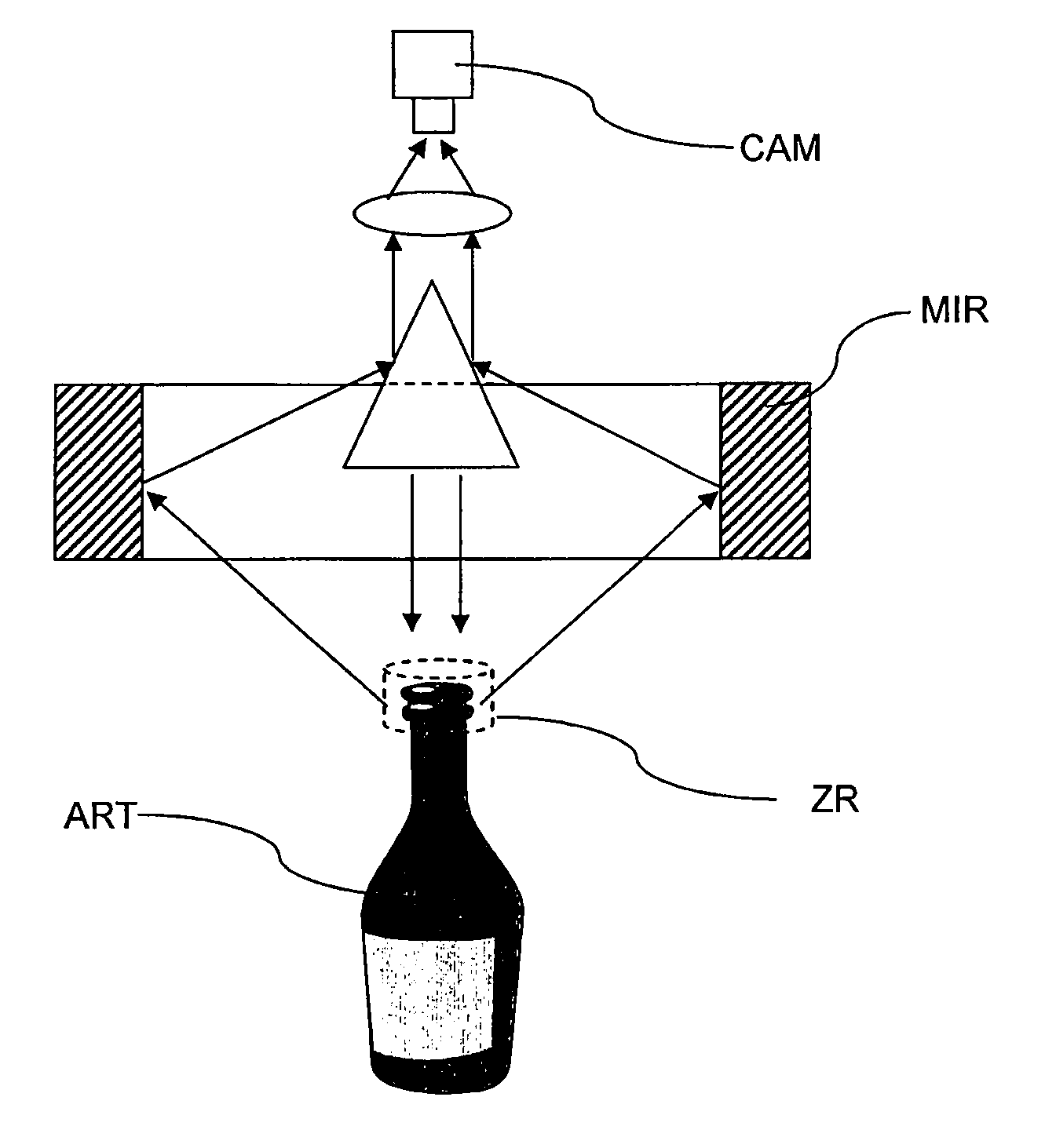
[0093]In a second embodiment, shown in FIG. 2, the viewing means comprise and optical head (not shown) provided with diffuse illumination , preferably positioned on the optical axis and configured to illuminate a glass article from above, and optical imaging means using an optical reflection of the image obtained of the illuminated article by a peripheral mirror MIR that has rotational symmetry and forms the image onto a camera CAM. The light emission / reception assembly is preferably rotationally symmetric.

[0094]By way of an alternative, the single peripheral mirror allowing a peripheral image of the finish to be obtained may be replaced by a circular assembly of facet mirrors juxtaposed with one another.

[0095]The mirror or the mirror assembly are preferably circular and the center of symmetry of these reflection means coincides with the center of symmetry of the finish of the article. The image of the finish is reflected toward a camera by means of an optical reflection device such...

first embodiment

[0101]In a first embodiment, the analysis mean are configured to detect automatically an optical signature of a defect. However, the drawback with optical fibers is that the images produced by the receiver assembly only allow construction of a partial image of the finish of the article being checked. Interpretation of the results is hence more difficult.

[0102]In a second embodiment, the analysis means are furthermore configured to process the images coming from the viewing means when these communicate a complete sample of the finish through a mirror assembly. In this case, the analysis means unroll the image so as to produce a flat image of all or part of the finish. The possible angular offset due to the random angular position of the article on the conveyor is compensated for by an angular reset step. This step is carried out by virtue of a reference mark preferably located on the article.

[0103]Whatever the embodiment, the analysis means comprise masking means that aim to eliminat...


PUM

PropertyMeasurementUnit
opticalaaaaaaaaaa
optical signatureaaaaaaaaaa
areaaaaaaaaaaa

Abstract

A device and method for detecting a defect in a finish ring of a glass article are described. The actual position of the finish ring is measured and enables a photographic device to be accurately positioned in relation to the finish ring, whereby the optical axis of the photographic device passes through the center of the finish ring. A sample of the finish ring is made and processed via an analyzing device configured so as to automatically detect an optical signature of the defect.

Description

BACKGROUND[0001](1) Field of the Invention[0002]The present invention relates to the field of the manufacture of glass articles, in particular operations for checking the finish ring, or finish, of an article.[0003](2) Prior Art[0004]The glass articles are, for example, industrially manufactured bottles or vials. These articles generally have defects such as surface cracks (tears), blisters, lack of material, excess of material, etc., the sizes and positions of which may be random.SUMMARY OF THE INVENTION[0005]More precisely, according to a first aspect, the invention relates to a method for detecting a defect in a finish of a glass article, comprising steps consisting in:[0006]viewing an image of a sample of the finish by viewing means comprising an optical axis; and[0007]processing the view by analysis means configured to detect an optical signature of the defect automatically.[0008]Such a method is known to the person skilled in the art. It is, for example, employed in a certain ...

Claims


Application Information

Patent Timeline
Patent Type & Authority Applications(United States)
IPC IPC(8): G01N21/90
CPCG01N21/9054
Inventor GAUFFRE, CHRISTOPHEHECKMANN, DIDIEROLLION, PIERRE
Owner SAVERGLASS
Why Eureka
Try Eureka