
Fiber optic adapter module and tray

a fiber optic adapter and fiber optic technology, applied in the field of fiber optic adapter modules and fiber optic equipment racks, can solve the problems of difficult hand access by technicians to optical components and connectors, difficult routing and organizing of jumper connections, and complex fiber management, etc., to achieve convenient access, convenient routing, and high density

Active Publication Date: 2009-03-12
CORNING OPTICAL COMM LLC
View PDF10 Cites 233 Cited by
  • Summary
  • Abstract
  • Description
  • Claims
  • Application Information

AI Technical Summary

Benefits of technology

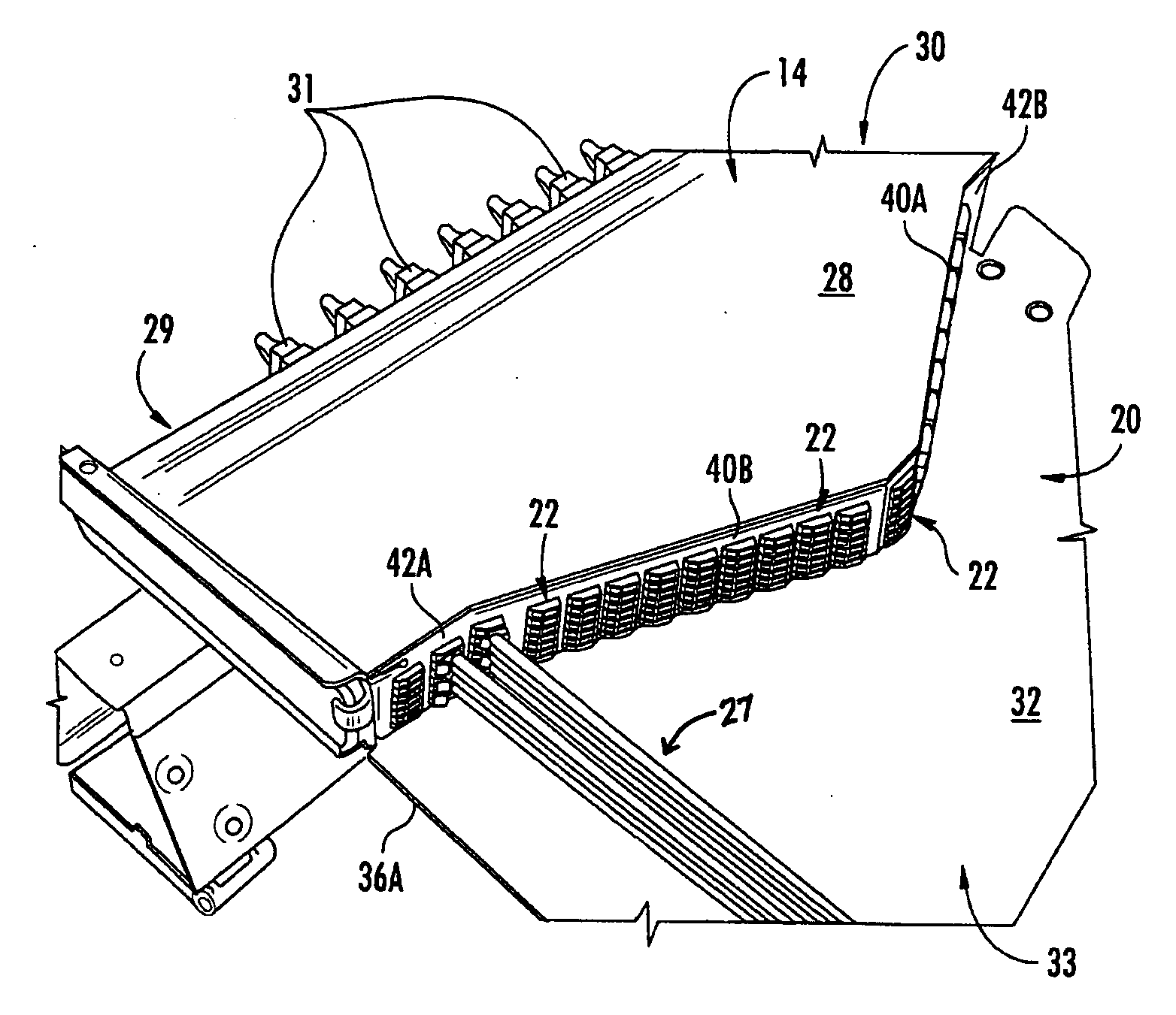
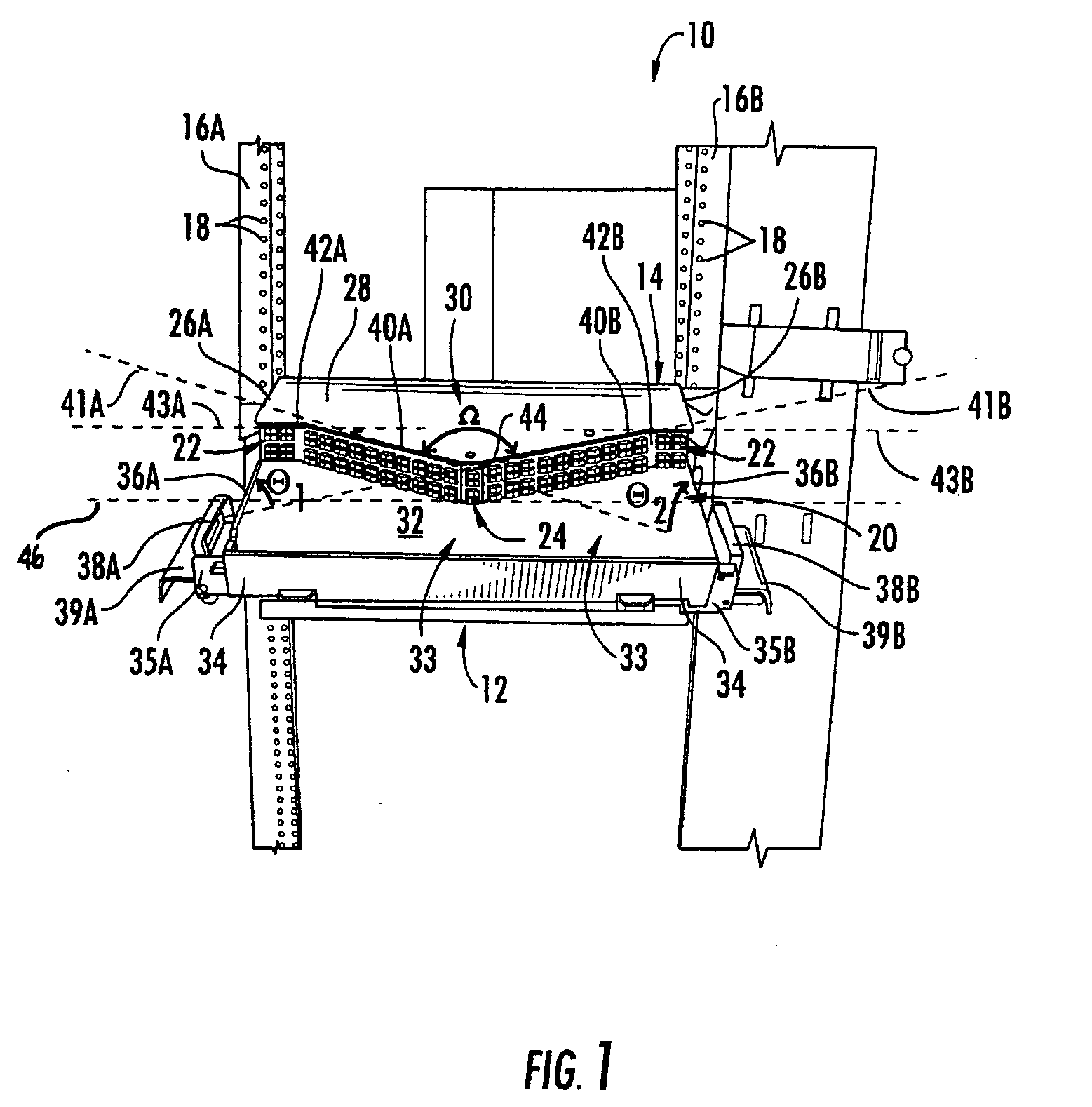
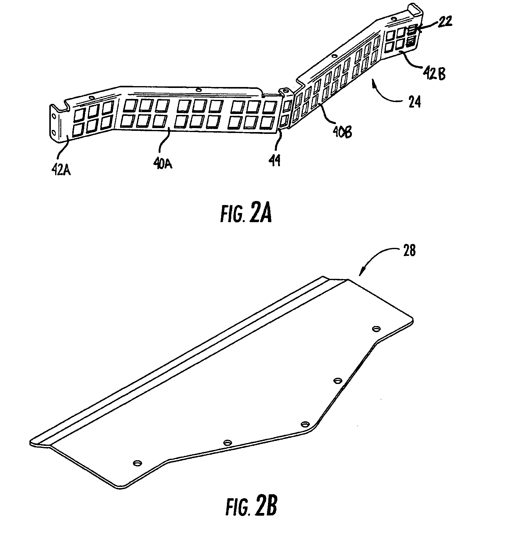
[0008]Embodiments disclosed in the detailed description include a fiber optic adapter module for supporting high density fiber optic connections. The fiber optic adapter module includes an adapter module panel supporting a plurality of fiber optic adapters that provides enhanced convenient access and neat routing and organizing of high density fiber optic connections. In one embodiment, the adapter module panel contains at least two forward facing panel surfaces angled to one another. Angled panel surfaces provide more surface area on the adapter module panel for supporting high density fiber optic adapters and increasing hand access space to the fiber optic adapters. A third and / or fourth flared panel surface may also be included on or proximate to ends of the adapter module panel and intersecting with the angled panel modules. Providing flared panel surfaces allows room for additional fiber optic adapters to be supported on or proximate to the ends of the adapter module panel for receiving optical connectors and also avoiding or reducing tight bending in fiber optic cables.
[0009]The fiber optic adapter module may also be provided in a fiber optic equipment tray that can be mounted in an equipment rack. To provide enhanced access to the fiber optic adapter module and to the fiber optic adapters supported therein, the fiber optic equipment tray contains an extendible tray. The fiber optic adapter module is coupled to the extendible tray. The extendible tray is coupled to a fixed portion of the fiber optic equipment tray and selectively extendible from an interior position within the fixed portion to a position generally external to the fixed portion. This allows the fiber optic adapter module to be extended out from an equipment rack to allow access to the fiber optic adapters and optical connections supported by the fiber optic adapter module. The extendible tray may also include a pivot mechanism configured to selectively tilt the extendible tray at a tilt angle relative to the fixed portion to provide enhanced access. This may be especially beneficial when a fiber optic equipment tray supporting a fiber optic adapter module is located in an equipment rack above technician arm height. The titling ability of the fiber optic equipment tray lowers the height of the fiber optic adapters and lowers arm height required to have a more direct line of access to the fiber optic adapters for making fiber optic connections.
[0010]Any type of optical fiber wiring scheme may be employed within the fiber optic adapter module. For example, a conventional networking solution employing a pair-wise fiber flip routing scheme that may be employed in the fiber optic adapter module. Alternatively, a universal optical fiber routing scheme may be employed whereby at least one of the optical fiber pairs routed by the fiber optic adapter module are are immediately adjacent in the fiber optic cable carrying the optical fibers. Using this networking module arrangement, multiple spans of assemblies can be interconnected. Fiber flips in the trunk assembly just prior to one end of a multi-fiber connector for polarity correction are not necessary, resulting in a complexity and / or cost reduction.

Problems solved by technology

Due to these higher connectivity density designs, fiber management is often complex and difficult due to the number of optical connections.
Higher density connections make it more difficult to access optical components and connections.
However, increased density makes hand access by technicians to optical components and connectors as well as the routing and organizing jumper connections more difficult.

Method used


Image

  • Fiber optic adapter module and tray
  • Fiber optic adapter module and tray
  • Fiber optic adapter module and tray

Examples


Embodiment Construction

[0008]Embodiments disclosed in the detailed description include a fiber optic adapter module for supporting high density fiber optic connections. The fiber optic adapter module includes an adapter module panel supporting a plurality of fiber optic adapters that provides enhanced convenient access and neat routing and organizing of high density fiber optic connections. In one embodiment, the adapter module panel contains at least two forward facing panel surfaces angled to one another. Angled panel surfaces provide more surface area on the adapter module panel for supporting high density fiber optic adapters and increasing hand access space to the fiber optic adapters. A third and / or fourth flared panel surface may also be included on or proximate to ends of the adapter module panel and intersecting with the angled panel modules. Providing flared panel surfaces allows room for additional fiber optic adapters to be supported on or proximate to the ends of the adapter module panel for ...


PUM


Abstract

A fiber optic adapter module and tray. The fiber optic adapter module supports fiber optic adapters for fiber optic connections. The fiber optic adapter module may be included on an extendible tray portion of a fiber optic equipment tray and selectively configured to be tilted when extended for providing enhanced access to the fiber optic adapter module. In one embodiment, an adapter module panel of the fiber optic adapter module that supports fiber optic adapters contains at least two forward facing panel surfaces angled to one another to provide more surface area for supporting a higher density of fiber optic adapters and / or for neat routing and organizing of fiber optic connections. One or more fourth flared panel surfaces may also be included on an end(s) of the adapter module panel to provide sufficient interior space for fiber optic connections adjacent or proximate to sides of the fiber optic equipment tray.

Description

RELATED APPLICATION[0001]The present application claims priority to U.S. Provisional Patent Application Ser. No. 60 / 967,798, filed on Sep. 7, 2007 and entitled “FIBER OPTIC ADAPTOR TRAY,” which is incorporated herein by reference in its entirety.BACKGROUND OF THE INVENTION[0002]1. Field of the Invention[0003]The present invention is related to a fiber optic adapter module and fiber optic equipment tray configured to support the fiber optic adapter module. The fiber optic adapter module and fiber optic equipment tray are configured to provide high density fiber optic connections and / or enhanced convenience to technicians in accessing fiber optic adapters for fiber optic cable connections.[0004]2. Technical Background[0005]Benefits of optical fiber use include extremely wide bandwidth and low noise operation. Because of these advantages, optical fiber is increasingly being used for a variety of applications, including but not limited to broadband voice, video, and data transmission. F...

Claims


Application Information

Patent Timeline
IPC IPC(8): G02B6/00
CPCG02B6/4452G02B6/4453G02B6/4455H04Q1/142G02B6/4401H04Q1/066A47B46/00A47B97/00A47B2097/003H04Q1/021
Inventor VAZQUEZ, MARIANO PEREZGONZALEZ, JUAN MIGUELESPARZA, FERNANDO M.VALDEZ, CESAR E.DENNIS, ROBERT W.UGOLINI, ALAN W.
Owner CORNING OPTICAL COMM LLC
Learn More