Imaging device and in-focus control method

Inactive Publication Date: 2009-03-12
SONY CORP
View PDF4 Cites 39 Cited by
  • Summary
  • Abstract
  • Description
  • Claims
  • Application Information

AI Technical Summary

Benefits of technology

[0009]It is therefore desirable to provide an imaging device that can stably perform high-speed and high-precision focus detection.
[0012]According to an embodiment of the present invention, a stop position of a focus lens is determined by adding a predetermined pass-through amount to a provisional position detected by performing focus detection based on a phase difference detection method. While the focus lens is being driven to move to the stop position through the provisional position, focus detection information used for focus detection based on a contrast detection method is obtained on the basis of image signals obtained by imaging means at individual positions of the focus lens at least within a given range of positions, and is stored in predetermined storage means. An in-focus position is detected based on the focus detection information stored in the predetermined storage means, and the focus lens is driven to the in-focus position. As a result, high-speed and high-accuracy focus detection can be stably performed.

Problems solved by technology

However, the hybrid AF method described above has a problem.
In such a case, quick focus detection is not achieved.

Method used


Image

  • Imaging device and in-focus control method
  • Imaging device and in-focus control method
  • Imaging device and in-focus control method

Examples


first embodiment

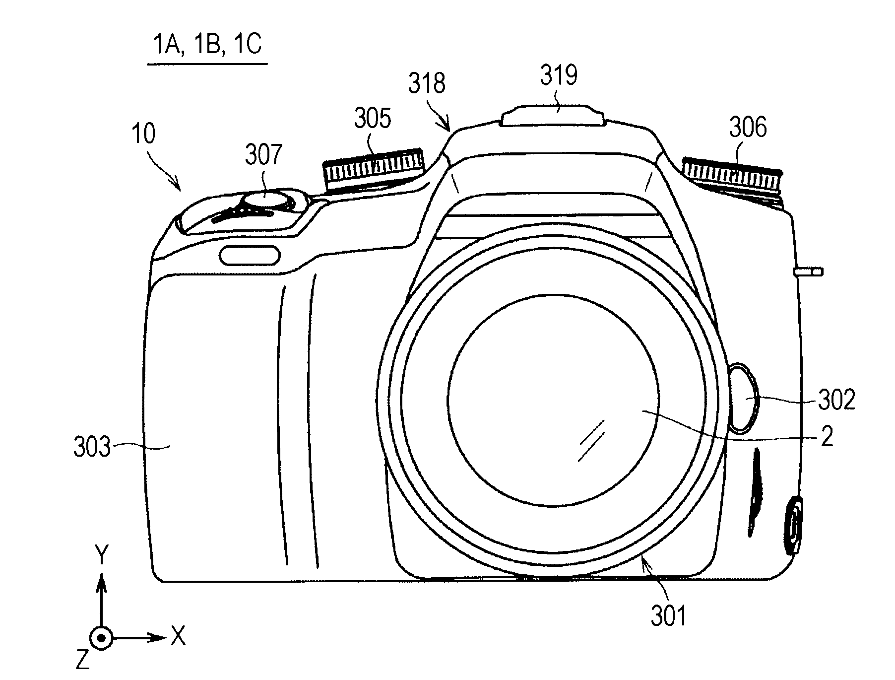
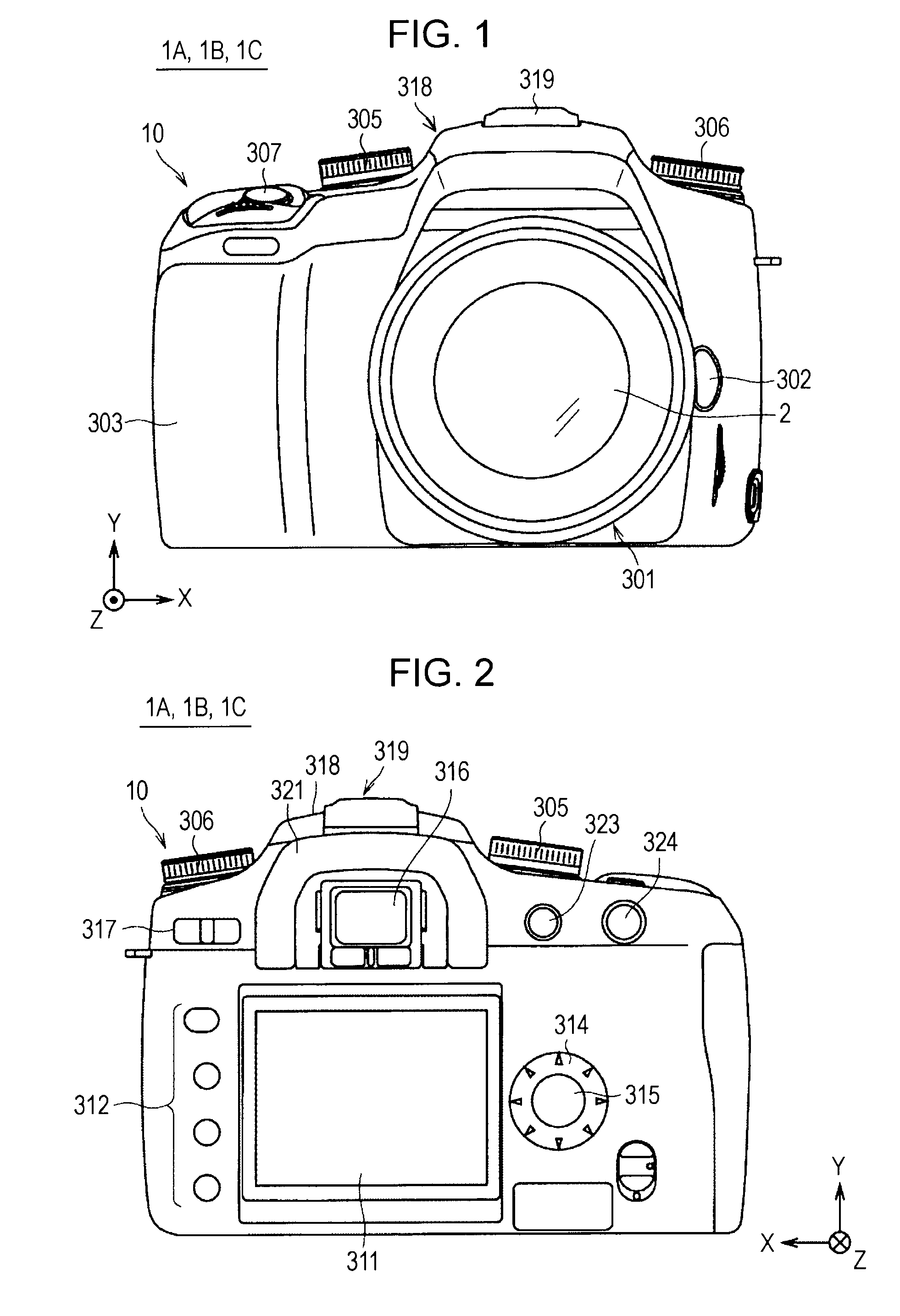
[0036]FIGS. 1 and 2 are diagrams showing an appearance structure of an imaging device 1A according to a first embodiment of the present invention. FIGS. 1 and 2 are front and rear views of the imaging device 1A, respectively.

[0037]The imaging device 1A is formed as, for example, a digital SLR still camera, and includes a camera body 10, and an interchangeable lens 2 serving as a photographic lens removably attached to the camera body 10.

[0038]Referring to FIG. 1, a mount portion 301 to which the interchangeable lens 2 is attached, a lens replacement button 302, a grip portion 303 that can be held by a user, a mode setting dial 305, a control value setting dial 306, and a shutter button 307 are provided on a front side of the camera body 10. The mount portion 301 is located at substantially the center of the front side of the camera body 10, and the lens replacement button 302 is located on the right side of the mount portion 301. The mode setting dial 305 is located at an upper left...

second embodiment

[0113]An imaging device 1B according to a second embodiment of the present invention has an appearance structure similar to that of the imaging device 1A of the first embodiment shown in FIGS. 1 to 2, but has a different internal structure.

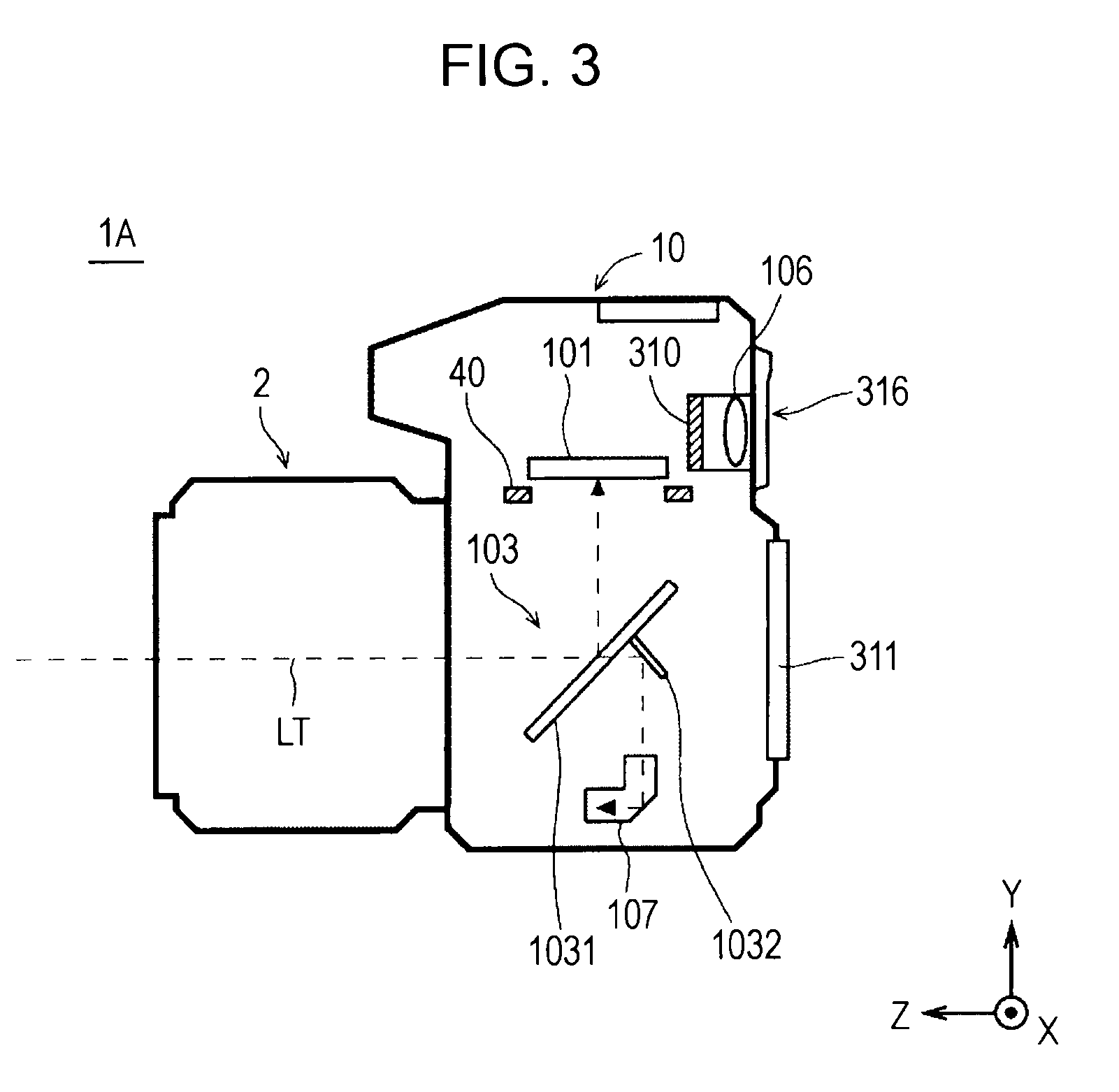
[0114]FIG. 8 is a longitudinal cross-sectional view showing an internal structure of the imaging device 1B.

[0115]The imaging device 1B includes an imaging element 101P (the details of which are described below) having a phase difference AF function. In the imaging device 1B, therefore, the phase difference AF module 107, which is provided in the imaging device 1A (see FIG. 3) of the first embodiment, is omitted.

[0116]In the imaging device 1B, furthermore, the mirror unit 103, which is provided in the imaging device 1A (see FIG. 3), is also omitted. Due to the absence of the mirror unit 103, the imaging element 101P and a shutter unit 40 are located in a plane perpendicular to an optical axis LT of an interchangeable lens 2.

[0117]An electrical stru...

third embodiment

[0137]An imaging device 1C according to a third embodiment of the present invention has an appearance structure similar to that of the imaging device 1A of the first embodiment shown in FIGS. 1 to 2, but has a different internal structure.

[0138]FIG. 19 is a longitudinal cross-sectional view showing an internal structure of the imaging device 1C.

[0139]The imaging device 1C is formed as a general digital SLR camera having an optical finder. The imaging device 1C has a camera body 10 in which an imaging element 101, a shutter unit 40, and a phase difference AF module 107, which have structures similar to those of the first embodiment, are provided. A mirror unit 103P having a structure similar to the mirror unit 103 of the imaging device 1A, and a finder unit (finder optical system) 102 are further provided. Unlike the first embodiment, the imaging element 101 and the shutter unit 40 are arranged in a plane perpendicular to an optical axis LT of an interchangeable lens 2.

[0140]The mirr...


PUM


Abstract

An imaging device includes an imaging unit that obtains an image signal relating to a subject, a driving unit that drives a focus lens, a first detecting unit that performs focus detection based on a contrast detection method to detect an in-focus position of the focus lens, a second detecting unit that performs focus detection based on a phase difference detection method, while the focus lens is being driven toward the in-focus position, to detect a provisional in-focus position of the focus lens, and an in-focus control unit that controls the driving unit to drive the focus lens to pass through the provisional in-focus position and then return to the in-focus position. Focus detection information is obtained at least for a given range of positions, and is stored in a predetermined storage unit. The in-focus position is detected based on the stored focus detection information.

Description

CROSS REFERENCES TO RELATED APPLICATIONS[0001]The present invention contains subject matter related to Japanese Patent Application JP 2007-235150 filed in the Japanese Patent Office on Sep. 11, 2007, the entire contents of which are incorporated herein by reference.BACKGROUND OF THE INVENTION[0002]1. Field of the Invention[0003]The present invention relates to an imaging device that allows focus detection based on a contrast detection method and focus detection based on a phase difference detection method.[0004]2. Description of the Related Art[0005]In general, imaging devices such as digital single lens reflex (SLR) cameras perform focus detection based on a phase difference detection method (phase difference AF) using phase difference AF sensors to perform auto-focus control (AF control). Phase difference AF has an advantage of quicker focus detection than focus detection based on a contrast detection method (contrast AF) in which a position of a focus lens at which image signals ...

Claims


Application Information

Patent Timeline
IPC IPC(8): G03B13/36
CPCG02B7/102H04N5/23212H04N5/23209G03B13/36H04N23/663H04N23/672H04N23/673H04N23/632
Inventor ONO, RIICHIFUJII, SHINICHIITO, TOMOOMI
Owner SONY CORP
Why Eureka
Try Eureka