Process for working metal material and structures

Inactive Publication Date: 2009-03-12
OSAKA UNIV +2
View PDF23 Cites 36 Cited by
  • Summary
  • Abstract
  • Description
  • Claims
  • Application Information

AI Technical Summary

Benefits of technology

[0021]With the method for processing metal materials in accordance with the present invention, the decrease in strength of the joining portion of friction stir welding caused by a fusion processing can be reduced and the joint strength can be

Problems solved by technology

The friction stir welding makes it possible to obtain a good joint strength, but such welding is difficul

Method used


Image

  • Process for working metal material and structures
  • Process for working metal material and structures
  • Process for working metal material and structures

Examples


Example

TEST EXAMPLE 1

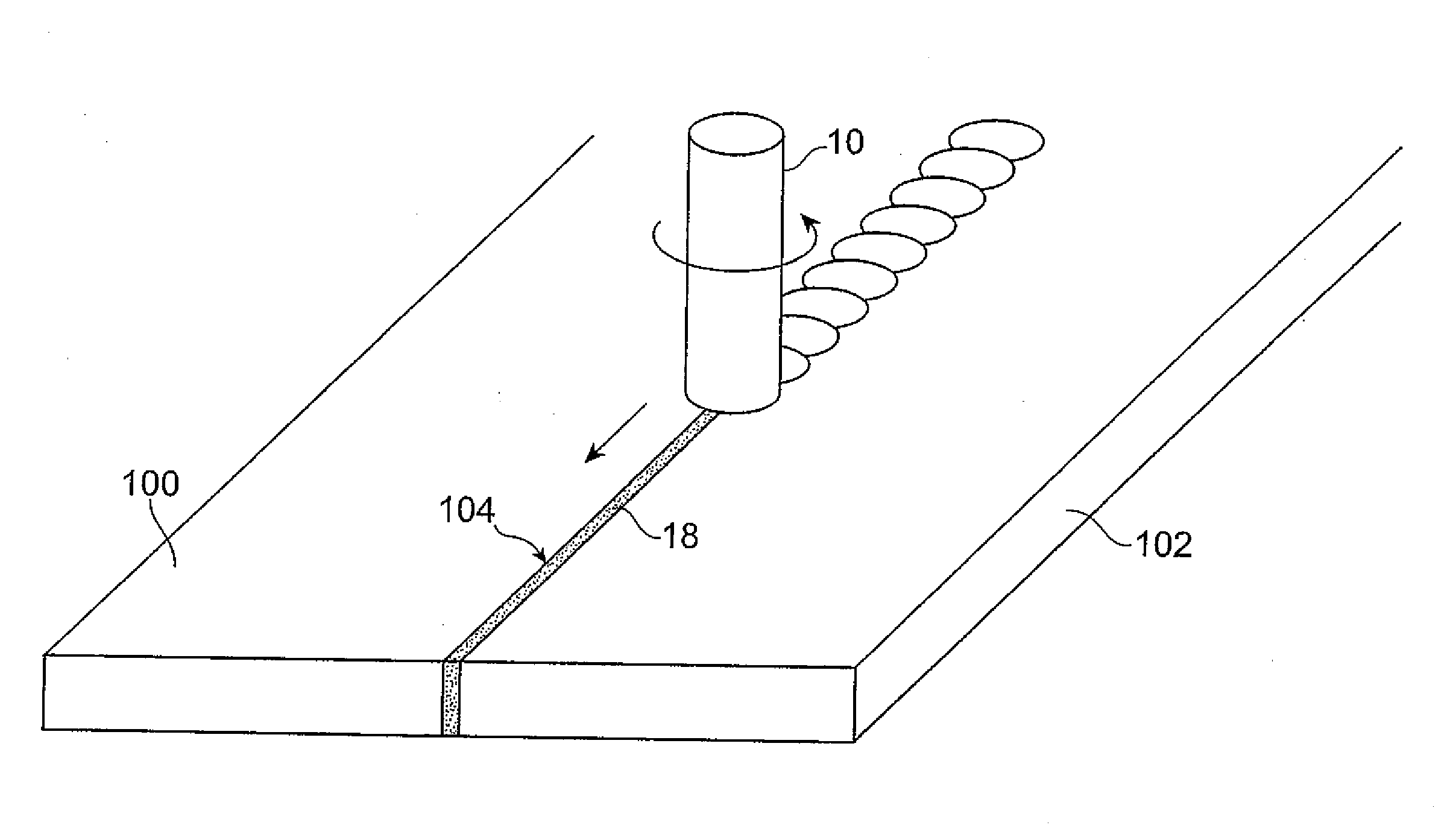
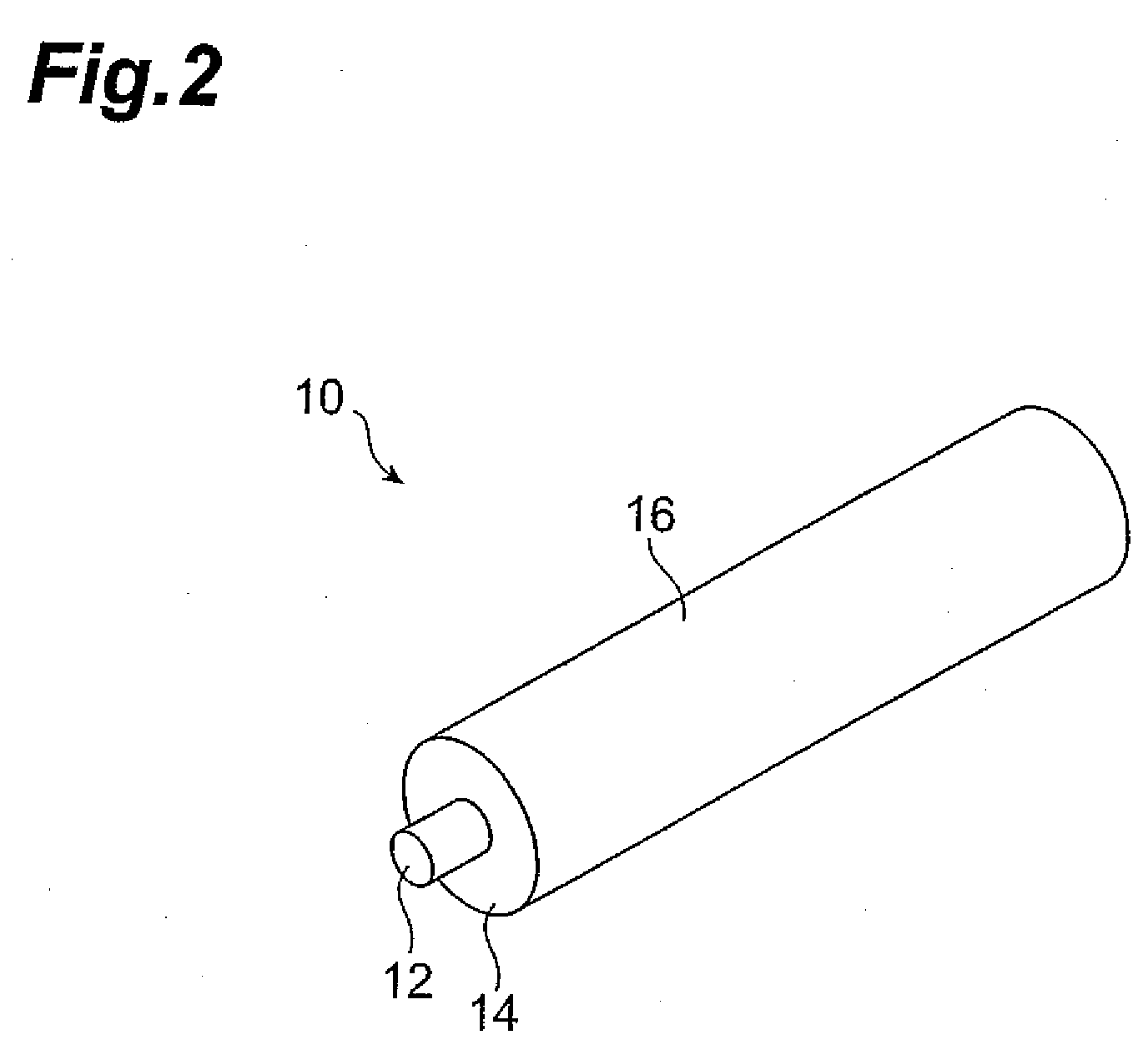
[0104]An AZ31 material (a Mg alloy containing Al 3% and Zn 1%) with a thickness of 6 mm was prepared. A groove with a width of 1 mm and a depth of 2 mm was formed at the surface of the prepared AZ31 material as an assumed joining portion where friction stir welding will be performed. A SiC powder 108 with a particle size of 0.5-5 μm and a mean particle size of 1 μm shown in FIG. 10 was charged into the formed groove. In the friction stir welding mode such as shown in FIG. 3, a probe 12 of a rotary tool 10 was inserted into the groove on the AZ31 material surface into which the SiC powder was charged, and a friction stir treatment was performed by moving the rotating rotary tool 10.

[0105]FIG. 11 illustrates the state of a zone where friction stir welding of the present test example was conducted. FIG. 12 is an enlarged drawing of an interface of a base material and a stirred zone. As shown in FIG. 11, it is clear that the state of crystal grains in a stirred zone 112 su...

Example

TEST EXAMPLE 2

[0114]An A1050 material, which is a material conforming to JIS H 4000, with a thickness of 6 mm was prepared. Similarly to the above-described Test Example 1, a groove with a width of 1 mm and a depth of 2 mm was formed at the surface, a SiC powder was charged into the groove, and a friction stir treatment was performed. The A1050 material subjected to the friction stir treatment was heat treated for 1 h at 300° C. For comparison, the heat treatment for 1 h at 300° C. was also performed with respect to an A1050 material subjected to friction stir treatment without the addition of SiC powder and an A1050 material that was not subjected to a friction stir treatment. The microhardness of the A1050 materials was measured before and after the heat treatment.

[0115]FIG. 31 is a graph illustrating the microhardness of the A1050 materials in the present test example. As shown in FIG. 31, in the A1050 material that was not subjected to a friction stir treatment, the difference i...

Example

TEST EXAMPLE 3

[0116]Two A1050 materials, which are materials conforming to JIS H 4000, with a thickness of 5 mm were prepared. As shown in FIG. 3, the A1050 materials were abutted in the joining portion, a TiC powder with an average particle size of 1 μm was charged into the joining portion, and friction stir welding was conducted at a revolution speed of a rotary tool of 500 rpm and a joining speed of 500 mm / min. The width of the joining portion obtained by the friction stir welding is 10 mm on the surface of the A1050 material. A melt-run welding was then performed by TIG welding at a joining speed of 200 mm / min at 180 A parallel into the joining portion from above the joining portion obtained by the friction stir welding. The width of the molten range was about 6 mm in the center of the A1050 material sheet in the thickness direction thereof. A hardness in the central portion of the sheet in the thickness direction in the transverse cross-section of the joining portion was therea...


PUM

PropertyMeasurementUnit
Fractionaaaaaaaaaa
Melting pointaaaaaaaaaa

Abstract

In a first step, friction stir welding is performed, while supplying a filler into a joining portion, in order to prevent the coarsening of crystal grains of metal materials in a subsequent fusion processing. Then, a fusion processing such as MIG welding is performed. The filler to be added to the joining portion includes a substance that does not chemically react with the metal materials and has a melting point higher than a melting point of the metal materials and a substance in which a misfit with the metal materials is within ±15%. As a result, the coarsening of crystal grains by the fusion processing is inhibited and the joint strength can be increased.

Description

TECHNICAL FIELD[0001]The present invention relates to a method for processing metal materials and a structure formed by the processing method.BACKGROUND ART[0002]A technique for welding metal materials by friction stir welding (FSW) is known among the conventional methods for processing metal materials. In friction stir welding, metal materials that are to be joined are disposed opposite each other in a joining portion, a probe provided at the distal end of a rotary tool is inserted into the joining portion, and the two metal materials are jointed together, while rotating the rotary tool, along the longitudinal direction of the joining portion. The friction stir welding makes it possible to obtain a good joint strength, but such welding is difficult to apply when the joining portion has a curved surface and when the rotary tool is difficult to insert. For this reason, when a structure such as a rail car body is manufactured by friction stir welding, the metal materials are processed...

Claims


Application Information

Patent Timeline
IPC IPC(8): B32B15/00B23K20/12
CPCB23K9/173B23K20/1255B23K20/128Y10T428/12493B23K28/02B23K2201/006B23K20/129B23K2101/006B23K20/122B23K20/16
Inventor FUJII, HIDETOSHIFUKUSUMI, MASAOMORISADA, YOSHIAKIISHIKAWA, TAKESHI
Owner OSAKA UNIV
Why Eureka
Try Eureka