Electronic Device With CPU and Interrupt Relay Stage

a technology of interrupt relay and electronic device, applied in the field of electronic device, can solve the problems of cpu active and consuming power, overall power consumption, adc may also need some time, etc., and achieve the effect of reducing power consumption

Inactive Publication Date: 2009-03-12
TEXAS INSTR INC
View PDF4 Cites 8 Cited by
  • Summary
  • Abstract
  • Description
  • Claims
  • Application Information

AI Technical Summary

Benefits of technology

[0006]It is an object of the present invention to provide an electronic device including a CPU with reduced power consumption.

Problems solved by technology

Further, the ADC may also need some time (conversion time) before valid digital output is available.
The CPU is active and consuming power during the time needed to settle the ADC.
Both the power consumed to power up the ADC and the power consumed by the CPU contribute to the overall power consumption.
Thus the CPU can not be switched off.
This often increases the power consumption.

Method used


Image

  • Electronic Device With CPU and Interrupt Relay Stage
  • Electronic Device With CPU and Interrupt Relay Stage
  • Electronic Device With CPU and Interrupt Relay Stage

Examples


Embodiment Construction

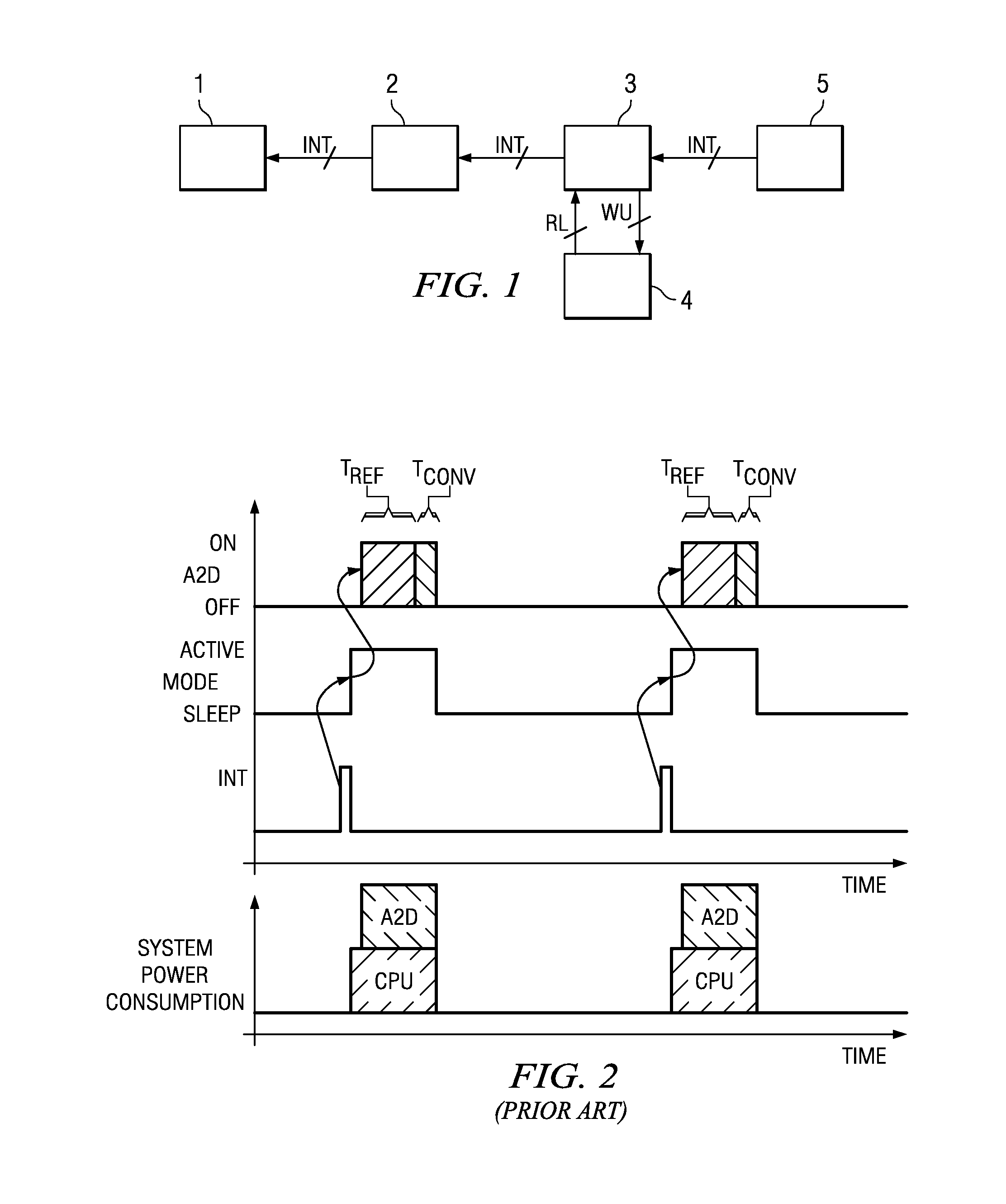
[0017]FIG. 1 illustrates a simplified schematic block diagram of an electronic device according to the invention. CPU 1 is coupled to an interrupt controller 2, from which receives interrupts. Interrupt controller 2 is coupled to interrupt relay 3. Interrupt relay 3 is coupled to a functional stage 4. Interrupt generator 5 generates an interrupt INT for input to interrupt relay 3. Interrupt generator 5 is representative for any device, stage or block that can generate an interrupt in response to an event. Functional stage 4 is functionally linked with the interrupt INT and is used during an active mode of CPU 1.

[0018]Functional stage 4 can be an analog voltage reference, an analog device, a complex digital system, such as a communications system, or a further control circuit. CPU 1 can be a standard microcontroller or a microprocessor.

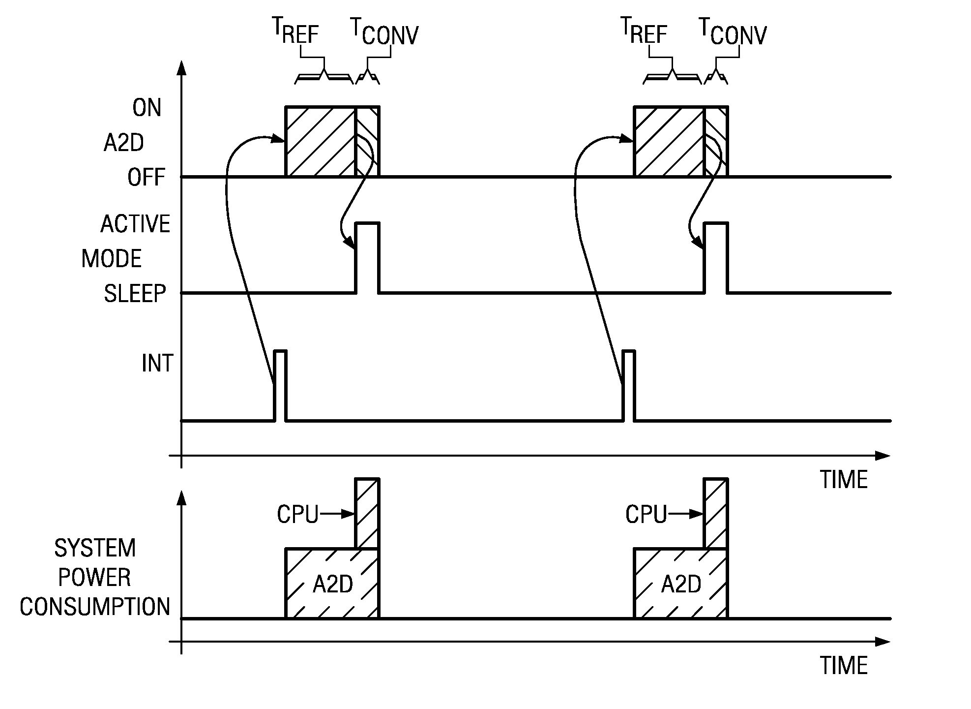
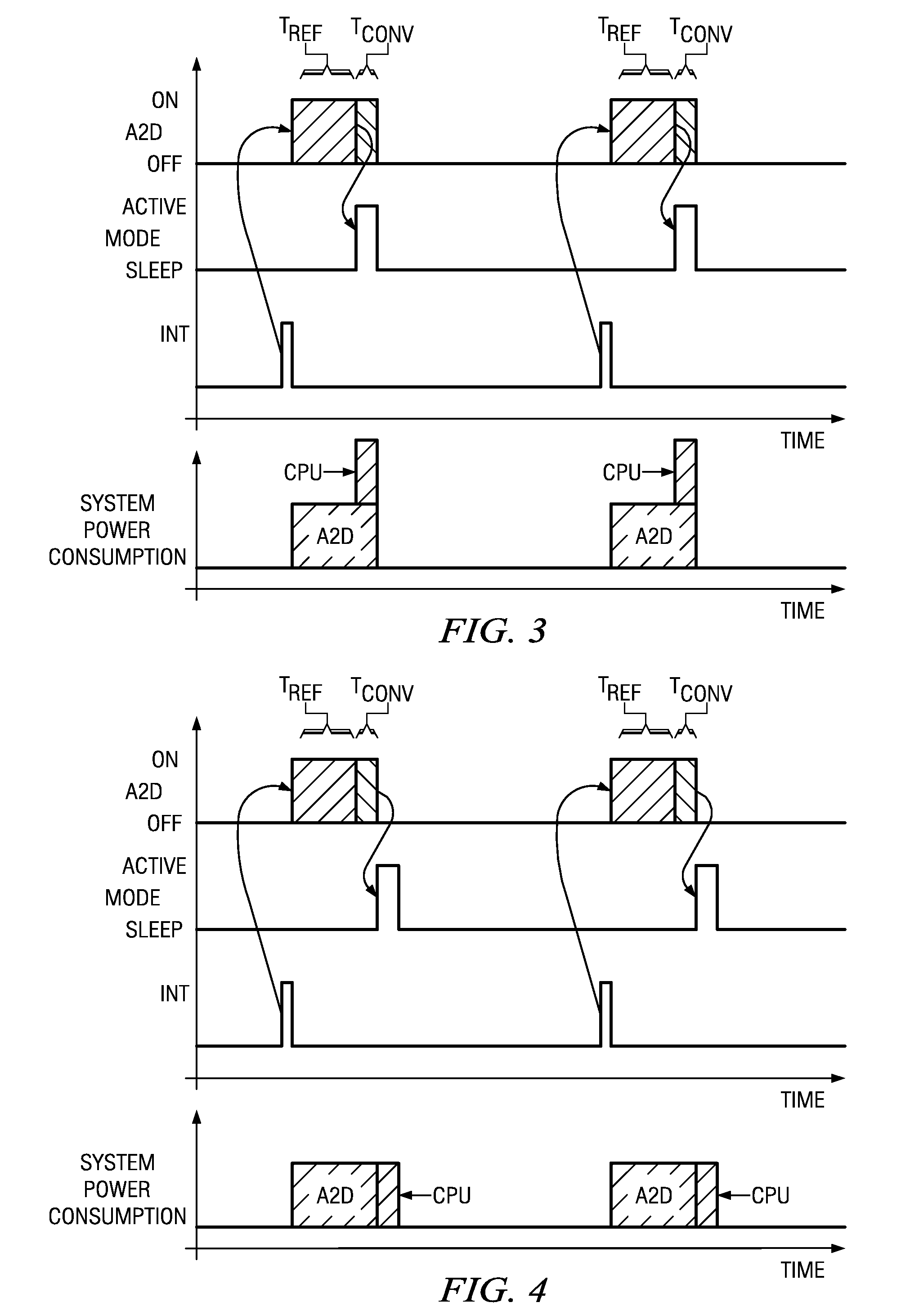
[0019]Interrupt relay 3 receives an interrupt INT from interrupt generator 5. Interrupt relay 3 then sends a wake up signal WU to functional stage 4. ...


PUM


Abstract

An electronic device with a CPU configured to be switched from a low power mode into a higher power mode in response to an interrupt and an interrupt relay coupled between an interrupt generator and the CPU. A functional stage is coupled to the interrupt relay and functionally linked with the interrupt so as to be used during the second mode of the CPU. The interrupt relay relays the received interrupt to the CPU only after a time needed for the functional stage to settle. Power is saved because the CPU is not powered while waiting for the functional stage to settle.

Description

CLAIM OF PRIORITY[0001]This application claims priority under 35 U.S.C. 119(a) to German Patent Application No. 10 2007 031 529.7 filed Jul. 6, 2007 and 35 U.S.C. 119(e)(1) to U.S. Provisional Application No. 61 / 016,728 filed Dec. 26, 2007.TECHNICAL FIELD OF THE INVENTION[0002]The technical field of this invention is an electronic device with a central processing unit and more particularly an interrupt control mechanism and a corresponding method.BACKGROUND OF THE INVENTION[0003]Applications or functionalities are often controlled by central processing units (CPUs) such as microcontrollers or microprocessors. Many applications only require a specific functionality or control task to be performed for a very short time. If not used the CPU enters into a sleep mode or inactive mode to reduce power consumption of the CPU to a minimum. The CPU can then be woken up by an interrupt signal (interrupt) to control or serve a functional stage linked with the interrupt. A functional stage linke...

Claims


Application Information

Patent Timeline
Patent Type & Authority Applications(United States)
IPC IPC(8): G06F9/30
CPCG06F13/24G06F1/3203
Inventor SCHREINER, JOERG
Owner TEXAS INSTR INC
Why Eureka
Try Eureka