Simultaneous-rotating hinge

Inactive Publication Date: 2009-03-19
SHIN ZU SHING
View PDF6 Cites 144 Cited by
  • Summary
  • Abstract
  • Description
  • Claims
  • Application Information

AI Technical Summary

Benefits of technology

[0007]The main objective of the present invention is to provide a simultaneous-rotating hinge that has a simple structure that facilitates manufacturin

Problems solved by technology

With technology improving, various types of hinges mounted in portable electronic devices have been developed and have gradually become more and more complex.
Thus, for some portab

Method used


Image

  • Simultaneous-rotating hinge
  • Simultaneous-rotating hinge
  • Simultaneous-rotating hinge

Examples


Embodiment Construction

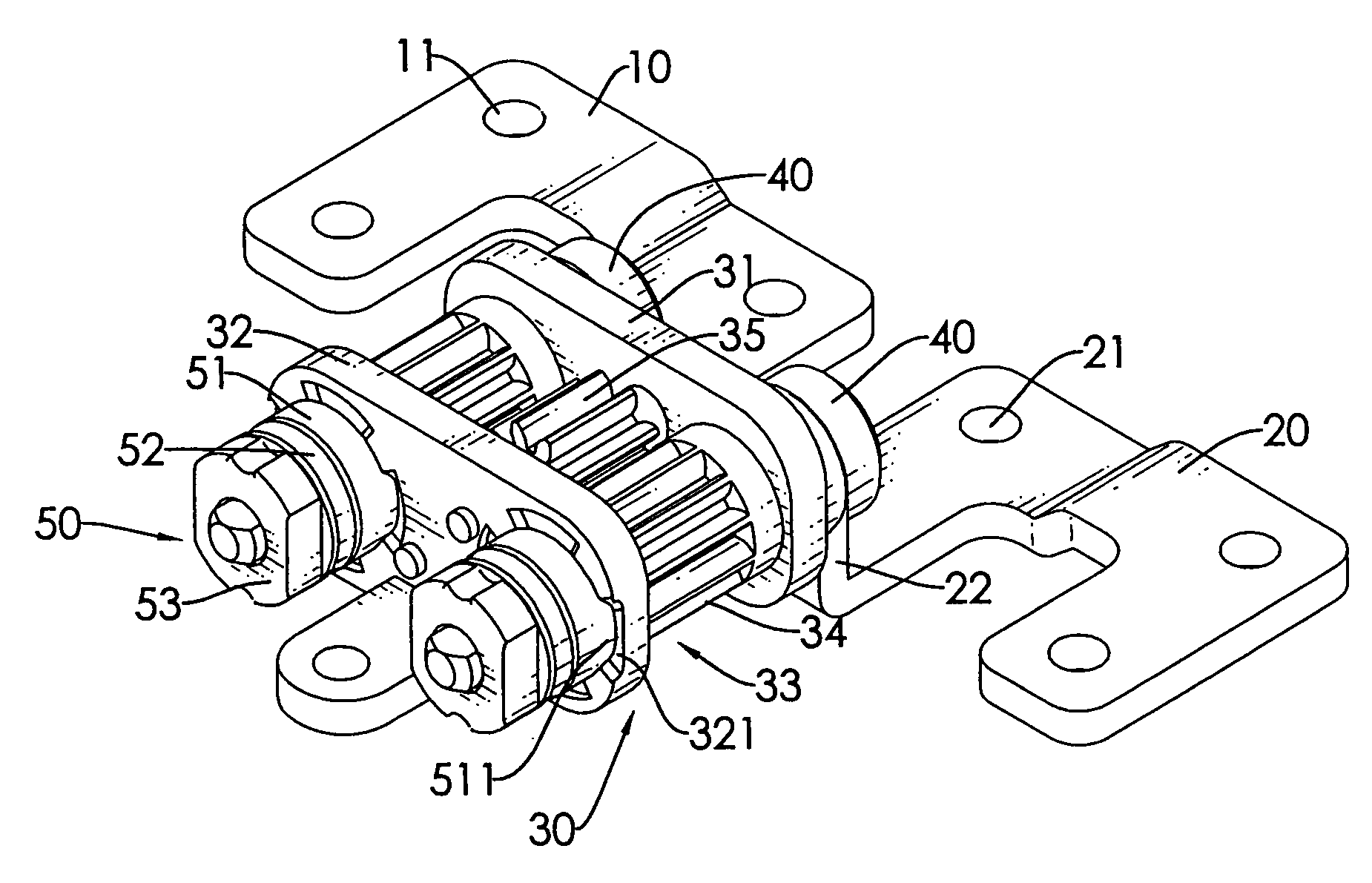
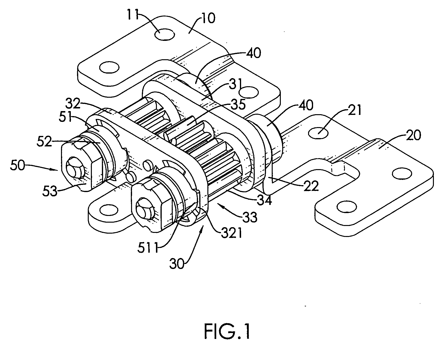
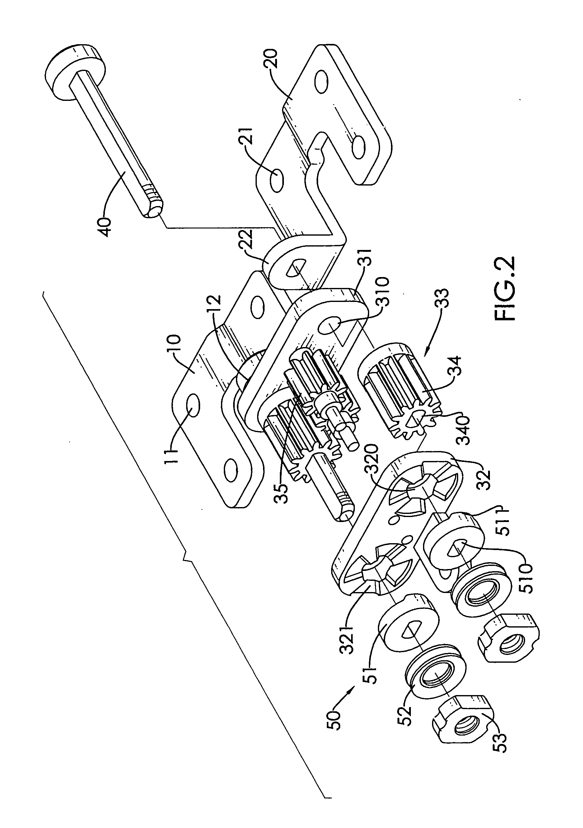
[0016]With further reference to FIGS. 1, 2 and 5, multiple simultaneous-rotating hinges in accordance with present invention are mounted on portable electronic devices (60) that include a cover (61) and a base (62), and the simultaneous- rotating hinge comprises a body (30), a first leaf (10) and a second leaf (20).

[0017]The body (30) has a frame, two mounting shafts (40), two positioning assemblies (50) and a gear assembly (33).

[0018]The frame comprises an outer mounting strip (31) and an inner mounting strip (32).

[0019]The outer mounting strip (31) has two ends, a middle, a top edge, a bottom edge, two shaft holes (310) and two pinholes. The shaft holes (310) are formed through the outer mounting strip (31) respectively near the two ends and are aligned with each other. The pinholes are formed near the middle of the outer mounting strip (31) and are offset respectively toward the top and bottom edges.

[0020]The inner mounting strip (32) is parallel to the outer mounting strip (31) ...


PUM


Abstract

A simultaneous-rotating hinge has a body, a first leaf and a second leaf. The body has a gear assembly. The gear assembly is mounted in the body and comprises multiple gears that engage each other. The first leaf is mounted rotatably on the body and connects to one of the gears in the gear assembly. The second leaf is mounted rotatably on the body and connects to another gear in the gear assembly. Interaction of the gears causes the first leaf and the second leaf to pivot simultaneously toward or away from each other.

Description

BACKGROUND OF THE INVENTION[0001]1. Field of the Invention[0002]The present invention relates to a hinge, and more particularly to a simultaneous-rotating hinge that facilitates manufacture and makes use of the hinge convenient.[0003]2. Description of Related Art[0004]Generally, a portable electronic device has a cover, a base and at least one hinge. The hinge is mounted between the cover and the base and allows the cover to pivot relative to the base.[0005]With technology improving, various types of hinges mounted in portable electronic devices have been developed and have gradually become more and more complex. However, a basic technique of operating the hinges still includes pivoting the cover toward the stationary base. The cover is rotated through a wide angle to cover the base. Thus, for some portable electronic devices, especially for portable electronic devices with covers and bases in a flat arrangement, pivoting the cover onto the base can be inconvenient and troublesome.[...

Claims


Application Information

Patent Timeline
IPC IPC(8): E05D7/00
CPCE05D3/122Y10T16/541E05Y2900/606E05D11/1078G06F1/1681
Inventor CHUNG, CHIA-KOLIN, YU-FENG
Owner SHIN ZU SHING
Why Eureka
Try Eureka