

Additive-agent diffusion plate structure in exhaust passage, and additive-agent diffusion plate in exhaust passage
- Summary
- Abstract
- Description
- Claims
- Application Information
AI Technical Summary
Benefits of technology
Problems solved by technology
Method used
Image

Examples
first embodiment
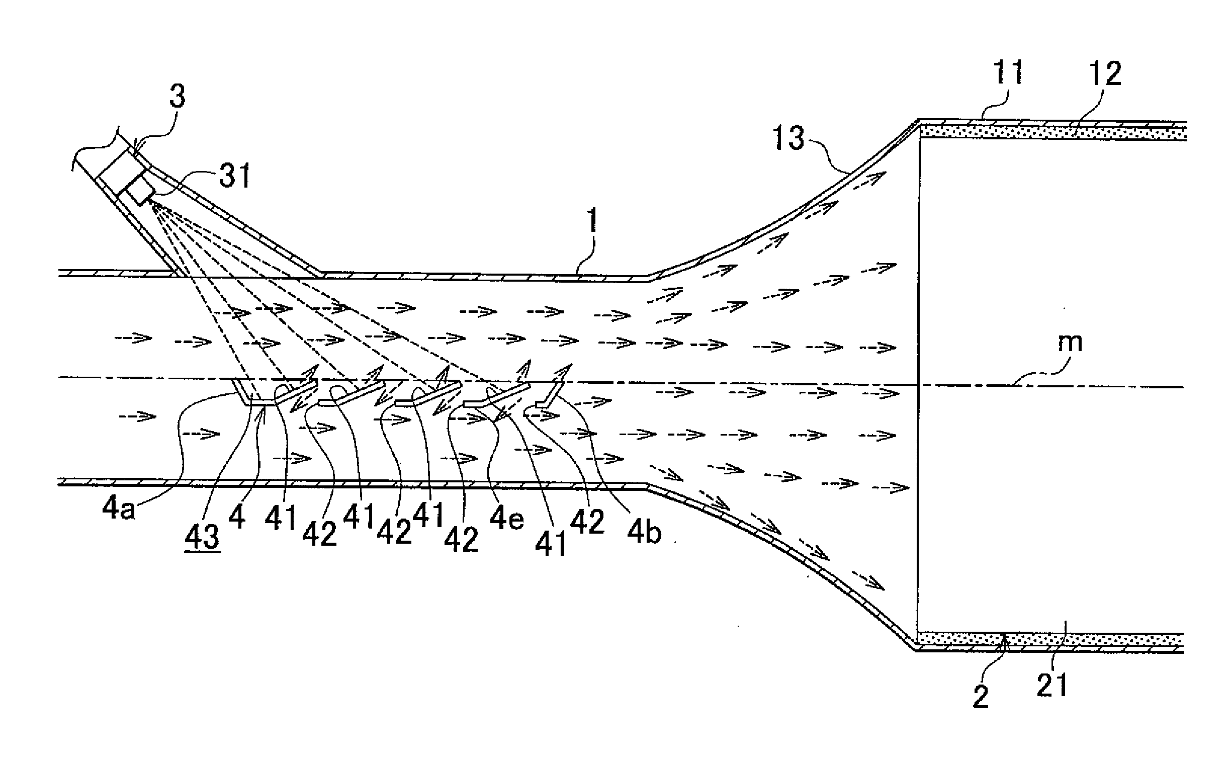
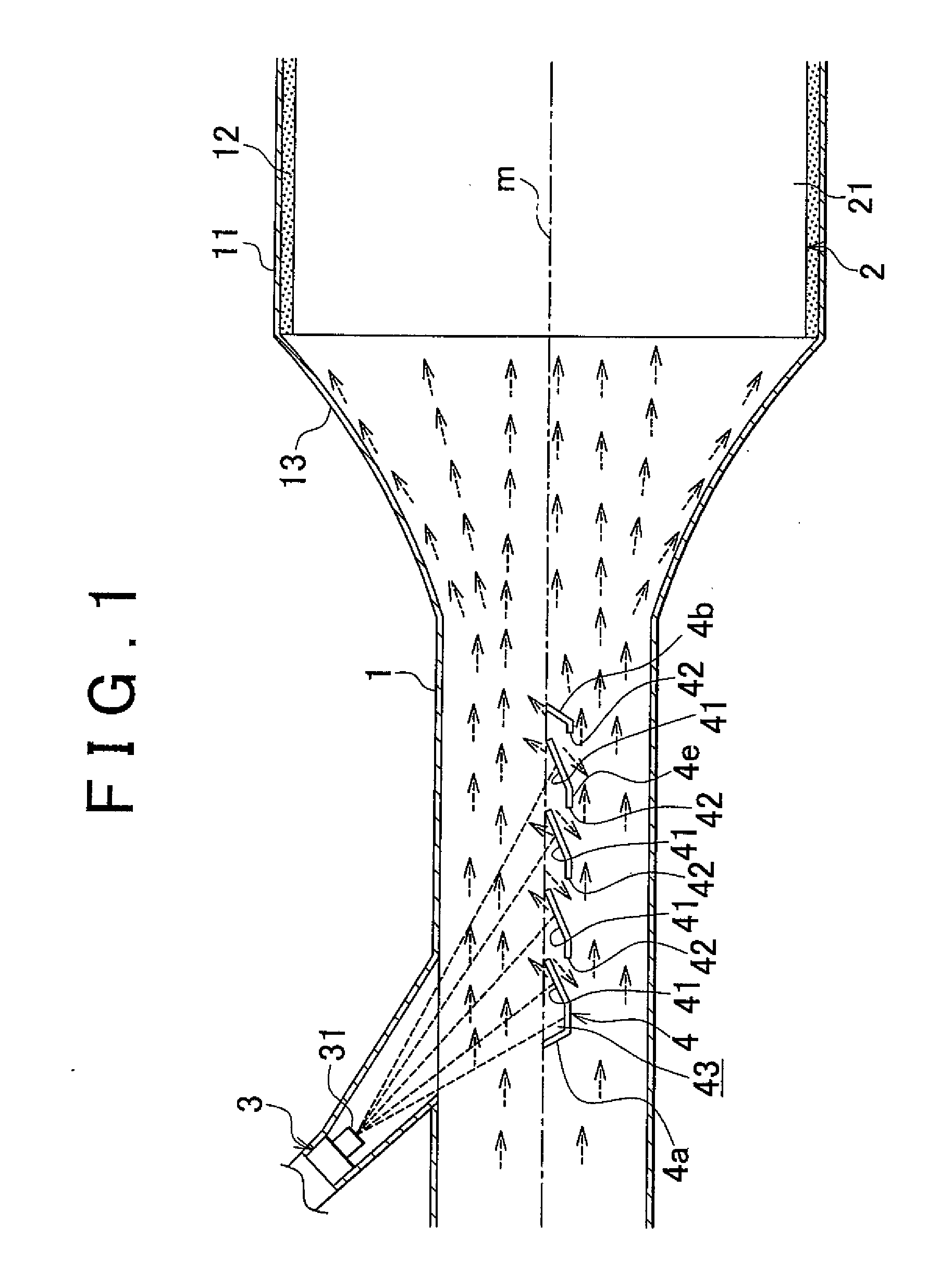
[0045]FIG. 1 is ah exhaust passage for a diesel engine for a vehicle (an example of the engine), in which an additive-agent diffusion plate structure according, to the invention is used. In FIG. 1, an exhaust gas purification device 2 is provided in an exhaust passage 1. The exhaust gas purification device 2 includes a selective reduction catalyst 21 that selectively causes nitrogen oxides (NOx) in exhaust gas to react with a reducing agent (an example of the additive agent) even in the presence of oxygen. The selective reduction catalyst 21 is provided inside a mat 12, in a large-diameter portion 11 of the exhaust passage 1, which has a large diameter. The large-diameter portion 11 is connected to another portion of the exhaust passage 1 by a warp portion 13 with a horn shape, which is warped toward an inside in a radial direction of the exhaust passage 1 from a downstream side toward an upstream side in a direction in which exhaust gas flows (hereinafter, referred to as “exhaust-g...
second embodiment
[0057]Next, the invention will be described with reference to FIG. 5.
[0058]In the second embodiment, the configuration of the diffusion plate is changed. The portions of the configuration other than the diffusion plate in the second embodiment is the same as the those in the first embodiment. Therefore, the same and corresponding portions as those in the first embodiment are denoted by the same reference numerals, and the detailed description thereof will be omitted.
[0059]That is, in the second embodiment, as shown in FIG. 5, a diffusion plate 5 includes an upstream end wall 5a, a downstream end wall 5b, a left end wall, and a right end wall. The upstream end wall 5a is formed by raising upward an upstream end of a bottom wall 5e. The downstream end wall 5b is formed by raising upward a downstream end of the bottom wall 5e. The left end wall 5c is formed by raising upward a left end of the bottom wall 5e. The right end wall 5d is formed by raising upward a right end of the bottom wa...
third embodiment
[0062]Next, the invention will be described with reference to FIG. 6 and FIG. 7.
[0063]In the third embodiment, the configuration of the injection nozzle and the configuration of the diffusion plate are changed. The portions of the configuration other than the injection nozzle and the diffusion plate in the third embodiment are the same as those in the first embodiment. Therefore, the same and corresponding portions as those in the first embodiment are denoted by the same reference numerals, and the detailed description thereof will be omitted.
[0064]That is, in the third embodiment, as shown in FIG. 6 and FIG. 7, an injection port 61 of an injection nozzle 6 is provided on the peripheral wall of the exhaust passage 1 at a side position, that is, on a horizontal line o (shown in FIG. 7) orthogonal to the axis m of the exhaust passage 1.
[0065]Also, the diffusion plate 7 is inclined toward the injection port 61 (for example, at approximately 45 degrees) with respect to a horizontal surf...
PUM
| Property | Measurement | Unit |
|---|---|---|
| Flow rate | aaaaa | aaaaa |
| Diameter | aaaaa | aaaaa |
| Length | aaaaa | aaaaa |
Abstract
Description
Claims
Application Information