Oil separator and refrigerant compressor having the same

a technology of oil separator and refrigerant compressor, which is applied in the direction of liquid fuel engine, separation process, lighting and heating apparatus, etc., can solve the problems of reducing the clearance between the inner surface of the separation cylinder and the outer surface of the refrigerant discharge pipe, reducing the distance of the refrigerant path from the refrigerant compressor to the oil separator, and reducing the pressure loss. , the effect of improving the oil separation efficiency

Inactive Publication Date: 2009-03-19
DENSO CORP +1
View PDF11 Cites 35 Cited by
  • Summary
  • Abstract
  • Description
  • Claims
  • Application Information

AI Technical Summary

Benefits of technology

[0012]Accordingly, the separation part restricts the separated oil from flying up. As such, the oil separation efficiency improves.
[0013]According to a third aspect of the present invention, such oil separators can be integrated with a refrigerant compressor. In such a case, a distance of refrigerant path from the refrigerant compressor to the oil separator is reduced. Therefore, pressure loss is reduced, and thus the oil separation e...

Problems solved by technology

Therefore, in a conventional oil separator, it is difficult to sufficiently separate the oil from the CO2 refrigerant by means of centrifugal force.
As a result, oil separation efficiency reduces.
In such a case, however, a clearance between an inner surface of the separation cylinder and an outer surface of a refrigerant ...

Method used


Image

  • Oil separator and refrigerant compressor having the same
  • Oil separator and refrigerant compressor having the same
  • Oil separator and refrigerant compressor having the same

Examples


first embodiment

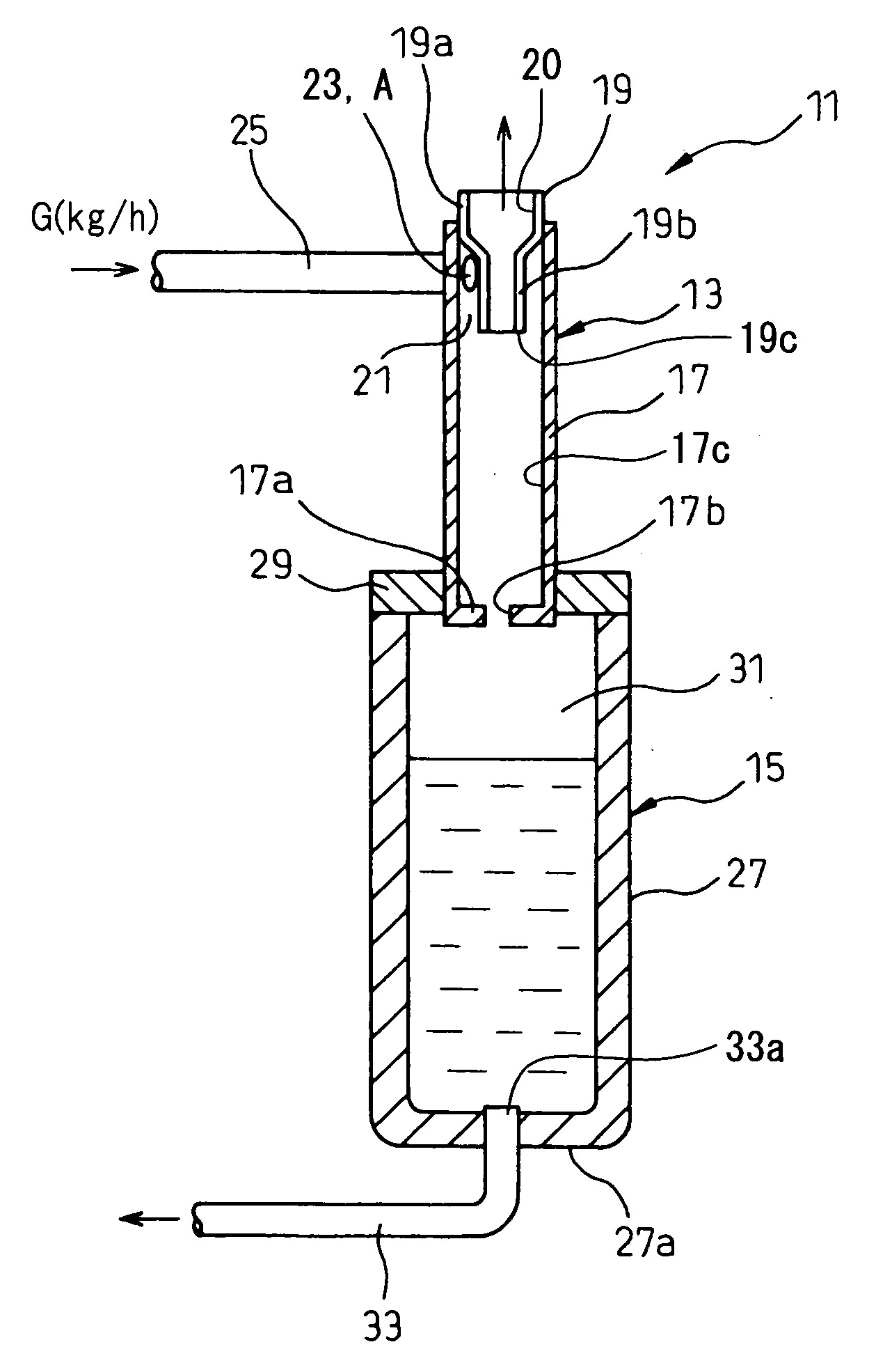
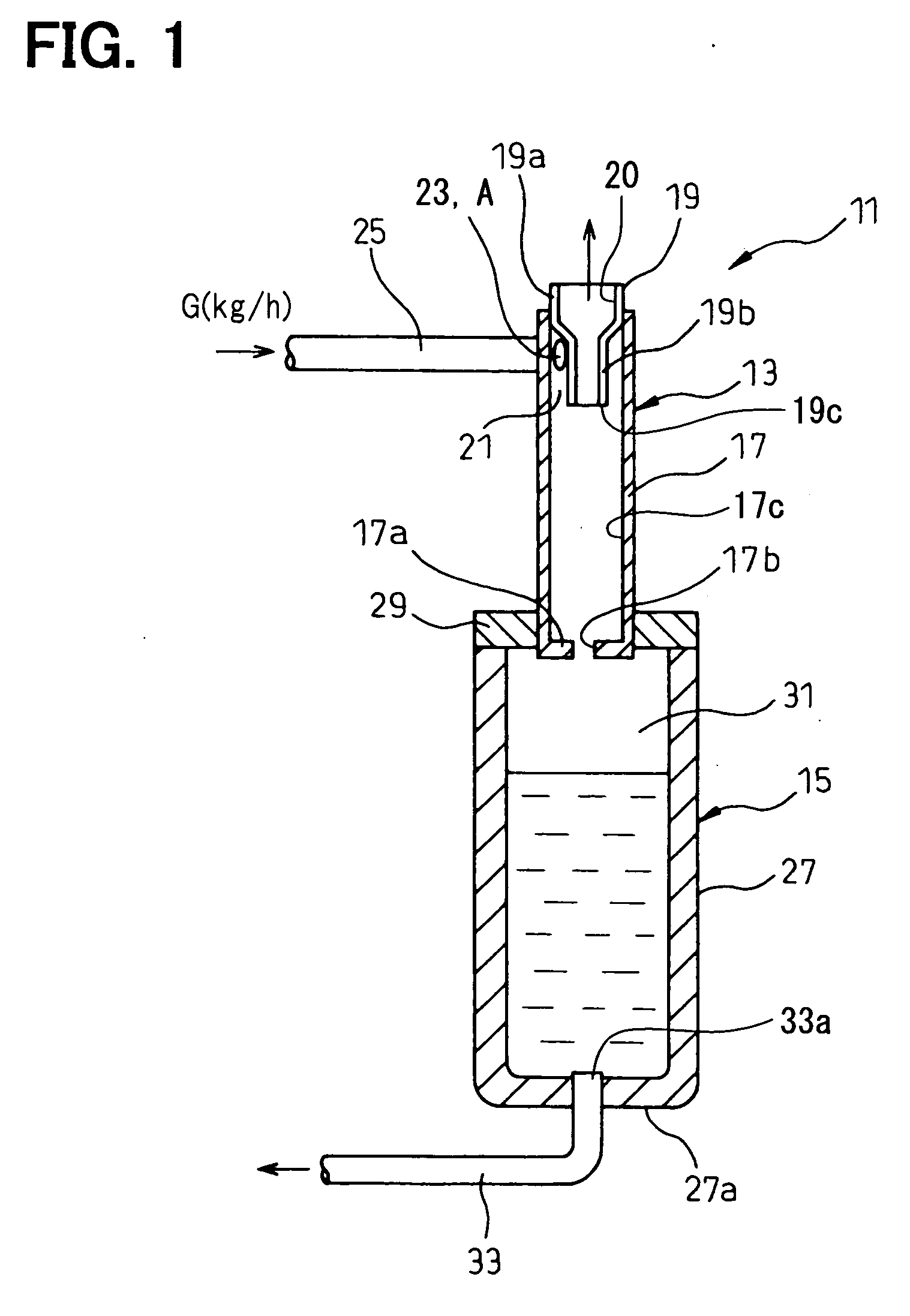
[0026]the present invention will be described with reference to FIGS. 1 to 4. Referring to FIG. 1, an oil separator 11 of the present embodiment is employed in a CO2 refrigerant cycle through which a CO2 refrigerant mainly containing CO2 circulates for a household apparatus, a vehicle air conditioner or the like. The oil separator 11 generally includes a separation part 13 and an oil storage part 15. The separation part 13 separates oil (lubricating oil) from the CO2 refrigerant. The oil storage part 15 stores the separated oil therein.

[0027]The separation part 13 includes a separation cylinder 17 and a refrigerant discharge pipe 19. The separation cylinder 17 has a tubular shape with a bottom end. An inner diameter of the separation cylinder 17 is substantially constant from a top end toward the bottom end. The top end of the separation cylinder 17 is open, and the refrigerant discharge pipe 19 passes through the top end of the separation cylinder 17.

[0028]The refrigerant discharge...


PUM

PropertyMeasurementUnit
Pressureaaaaaaaaaa
Ratioaaaaaaaaaa

Abstract

An oil separator includes a separation part and an oil storage part. The separation part includes a separation cylinder, an inner cylinder disposed in the separation cylinder and an inlet pipe connecting to the separation cylinder tangential to an inner surface of the separation cylinder. The separation part defines an inlet opening to introduce CO2 refrigerant containing oil in the separation cylinder. The separation cylinder separates the oil from the CO2 refrigerant by means of centrifugal force. A ratio of a flow rate (kg/h) of the CO2 refrigerant flowing in the separation cylinder to an area (mm2) of the inlet opening is at least 4. Alternative to or in addition to the above, a ratio of a distance (mm) from an end of the inner cylinder to a bottom wall of the separation cylinder to an inner diameter (mm) of the separation cylinder is at least 2.5.

Description

CROSS REFERENCE TO RELATED APPLICATION[0001]This application is based on Japanese Patent Applications No. 2007-242625 filed on Sep. 19, 2007, No. 2007-282739 filed on Oct. 31, 2007 and No. 2008-147395 filed on Jun. 4, 2008, the disclosure of which are incorporated herein by reference.FIELD OF THE INVENTION[0002]The present invention relates to an oil separator for separating oil from gas refrigerant by means of centrifugal force and a refrigerant compressor having the oil separator.BACKGROUND OF THE INVENTION[0003]In general, a compressor of a refrigerant cycle is lubricated by a lubricating oil mixed with gas refrigerant. If the oil is discharged from the compressor into the refrigerant cycle with the gas refrigerant, a coefficient of performance (hereinafter, system COP) of the refrigerant cycle is reduced. The system COP is reduced as the amount of the oil discharged from the compressor is increased. It is known to arrange a centrifugal oil separator at an outlet of the compresso...

Claims


Application Information

Patent Timeline
IPC IPC(8): F25B43/02
CPCB01D45/12F04C18/0215F04C23/008F04C29/026F04C2210/1027F25B2500/01F04C2240/30F04C2240/806F04C2240/809F25B43/02F25B2400/02F04C2210/1072
Inventor KUSADA, TAKASHIKAWAMOTO, YOICHIROHOTTA, TADASHIIWANAMI, SHIGEKI
Owner DENSO CORP
Why Eureka
Try Eureka