Spring apparatus and accelerator pedal apparatus
a technology of accelerator pedal and spring, which is applied in the direction of mechanical control devices, instruments, process and machine control, etc., can solve the problems of damper b>17/b> generating abnormal noise, coil spring vibrating and thereby generating abnormal noise (spring noise), etc., and achieve the effect of reliably limiting the noise of double coil spring over a long period of tim
- Summary
- Abstract
- Description
- Claims
- Application Information
AI Technical Summary
Benefits of technology
Problems solved by technology
Method used
Image
Examples
first embodiment
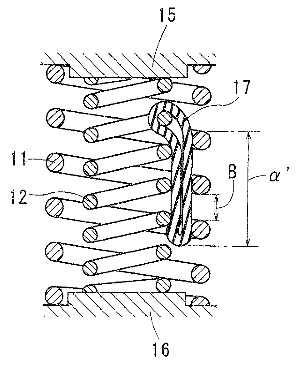
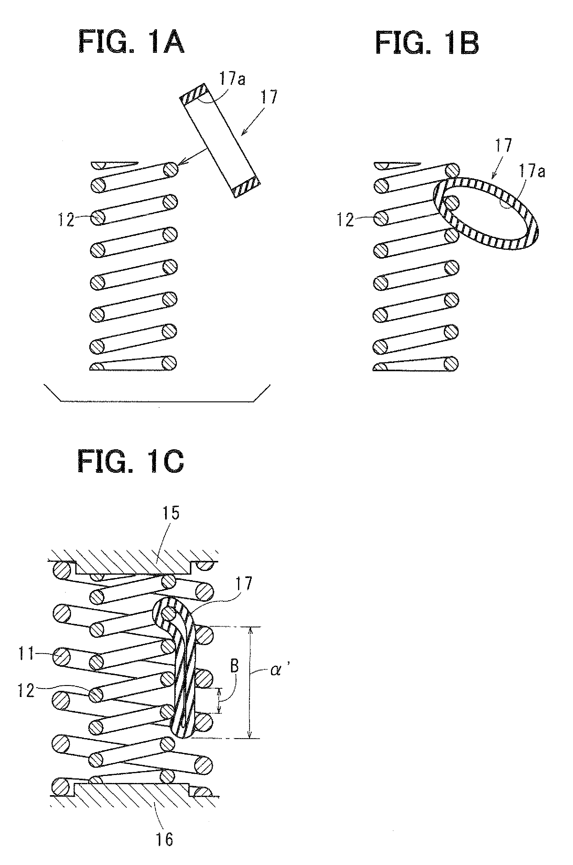
[0034]An accelerator pedal apparatus having a spring apparatus, to which the invention is applied, is described below with reference to FIGS. 1A to 3. The accelerator pedal apparatus controls an operational state of an engine for vehicle traveling according to pedal force applied to a accelerator pedal 1 by a driver. In a first embodiment of the invention, a throttle-by-wire method is employed, and the accelerator pedal 1 is not mechanically connected with a throttle apparatus of a vehicle. Instead, in the accelerator pedal apparatus, a rotation angle of the accelerator pedal 1 is detected by a rotational angle sensor 2, and then a signal indicating the detection result is outputted to an electronic control unit (ECU: engine control unit) of the engine of the vehicle. Accordingly, the ECU controls a throttle apparatus based on the rotation angle of the accelerator pedal 1 obtained from the output signal from the rotational angle sensor 2.
[0035]An example of the accelerator pedal app...
second embodiment
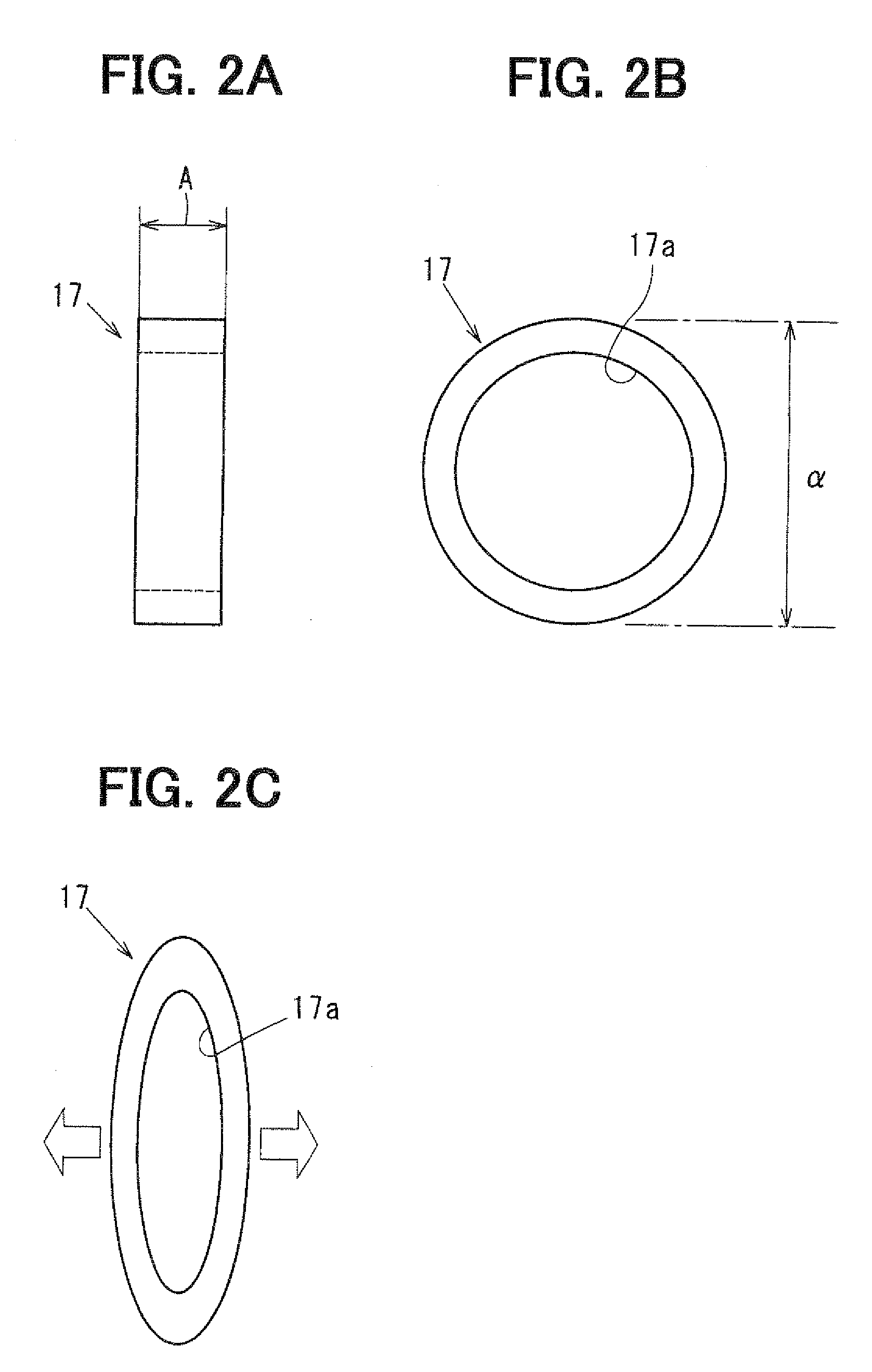
[0052]A second embodiment of the invention is described below with reference to FIGS. 4A to 4D. In addition, the same numerals in the following embodiments as the first embodiment indicate the same corresponding functional components as those in the first embodiment. As shown in FIGS. 4A, 4B, a damper 17 of the second embodiment has ring portions 17a respectively at both its ends. The damper 17 of the second embodiment is formed such that “a width A of the damper 17 in a direction perpendicular to the ring of the ring portion 17a of the damper 17” is small. The above width A is set such that a relation of A≧C is satisfied so that the damper 17 is reliably in contact with both the outer coil spring 11 and the inner coil spring 12, provided that a clearance between an outer coil spring 11 and an inner coil spring 12 in their radial direction is C.
[0053]Attachment of the damper 17 of the second embodiment is described below. First, as shown in FIG. 4C, a free end of the inner coil spri...
third embodiment
[0056]A third embodiment of the invention is described below with reference to FIGS. 5A, 5B. In the third embodiment, similar to the second embodiment, a damper 17 is provided with ring portions17a respectively at both its ends. However, the damper 17 of the third embodiment is formed such that “a width A of the damper 17 in a direction perpendicular to the ring of the ring portion 17a of the damper 17” is larger than that of the second embodiment. Similar to the first embodiment, the width A is larger than “a maximum gap B between lines of the outer coil spring 11 and the inner coil springs 12 in the initial set state in which the double coil spring is attached to the accelerator pedal apparatus” (A>B).
[0057]The procedures of the attachment are similar to those of the second embodiment. However, because the width A of the damper 17 is thinly formed in the second embodiment, when covering the inner coil spring 12 with the outer coil spring 11 from its upper side, the ring of the rin...
PUM
 Abstract
Description
Claims
Application Information
 - R&D
- Intellectual Property
- Life Sciences
- Materials
- Tech Scout
- Unparalleled Data Quality
- Higher Quality Content
- 60% Fewer Hallucinations
Browse by: Latest US Patents, China's latest patents, Technical Efficacy Thesaurus, Application Domain, Technology Topic, Popular Technical Reports.
© 2025 PatSnap. All rights reserved.Legal|Privacy policy|Modern Slavery Act Transparency Statement|Sitemap|About US| Contact US: help@patsnap.com


