
Drive for displacing profile parts relative to each other via a flexible material strip, length-adjustable housing and article of furniture

a technology of flexible material and drive, which is applied in the direction of furniture parts, variable height tables, gearing, etc., can solve the problems of low efficiency, low construction efficiency, and low efficiency of existing spindle/nut transmissions, and achieves improved drive for relative displacement of profile parts, simple and inexpensive construction, and large adjustment range

Active Publication Date: 2009-03-19
ACTIFORCE INT BV
View PDF10 Cites 22 Cited by
  • Summary
  • Abstract
  • Description
  • Claims
  • Application Information

AI Technical Summary

Benefits of technology

[0006]The present invention therefore has for its object to provide an improved drive for relative displacement of profile parts with a simple and inexpensive construction, whereby a relatively large adjustment range can be realized.
[0009]It is also possible that the drive shaft is embodied for manual operation such as a crank. Such a drive has the significant advantage over the prior art drives that the friction losses in the transmission are very low, whereby the motor can take a very light (and therefore compact and inexpensive) form. This makes it possible in more applications than heretofore to arrange the (electric) motor in the first profile part. An additional consequence of the relatively light construction is that the drive produces very little noise during use. This can be particularly advantageous in specific applications. Another advantage is that the drive according to the present invention allows great freedom in the design thereof. Subject to the application, a choice can thus be made in respect of the guiding (for instance a simple pin or an optionally mounted reversing wheel), the drive wheel and the flexible material strip (more on this below). A further significant advantage is that standard profile parts can be applied without having to undergo a particular processing on the inside. The complete drive can be manufactured at relatively low cost and, owing to the simple construction, is also little susceptible to malfunction.
[0010]For proper operation of the drive it is desirable that the drive wheel engages substantially without slip on the flexible material strip. In a preferred embodiment the drive wheel can be provided for this purpose with a toothing, and the flexible material strip can be provided with a profiling co-acting with the toothing of the drive wheel. Since the flexible material strip can only be engaged by the drive wheel over a part of the length, it is also possible for the flexible material strip to be assembled from successive segments with varying material properties. The part of the flexible material strip which engages with the drive wheel can for instance be formed by a chain or a toothed belt, while the part of the flexible material strip which does not engage with the drive wheel can take a less expensive form, for instance by opting for hoop-steel.
[0013]In yet another preferred embodiment the second profile part is provided with an additional guide by which an additional flexible material strip connected on one side to the first profile part is guided, which strip is connected on the opposite side to a guide connected to the third profile part. The additional flexible material strip can herein be connected to a protruding element which is rigidly connected to the third profile part. The third profile part herein preferably engages round the first and the second profile part, and the protruding element connected to the third profile part is located in the internal space of the first profile part. With such an expansion of the drive according to the invention it becomes possible to also displace a third profile part relative to the two other profile parts. A telescopic construction thus becomes possible with three (or even more than three) profile parts extendable and retractable relative to each other. The third profile part as it were “goes along” with the displacement brought about between the first and second profile parts. No additional driving (motor) is required for this purpose; the motor which drives the displacement between the first and second profile parts will of course have to be dimensioned such that power remains available for the displacement of the third profile part. It is noted that the invention can be expanded still further with an nth profile part provided with an additional guide whereby an additional flexible material strip connected on one side to the first profile part (or a random other profile part up to and including the (n−1)th) is guided, which strip is connected on the opposite side to a guide connected to an (n+1)th profile part. In this way the number of segments of which a telescopic construction can consist can (theoretically) be extended infinitely.
[0015]In order to increase the stability when moving the profile parts apart, it is also possible for the drive to comprise two flexible material strips which are rigidly connected on at least one side to a second profile part, which material strips also engage on the drive wheel, and two guides for the flexible material strips connected in stationary manner to the first profile part. It will be apparent that other components of the drive according to the present invention can also take a multiple form (twice as many or an even greater multiple) so as to increase the convenience of use, the stability and / or the reliability of the construction.
[0017]For a simple operation of the drive, the housing can be provided with operating means for activating a motor connected to the drive. A control panel connected to the housing can be envisaged here, or an optionally wireless control panel for placing remotely of the housing. Alternatively or additionally, it is also possible for the housing to be provided with a control member with which the drive wheel can be rotated manually.

Problems solved by technology

A drawback of the existing systems is that generally they are relatively costly and heavy and have a complex construction.
The existing spindle / nut transmissions also have a limited adjustment range.

Method used


Image

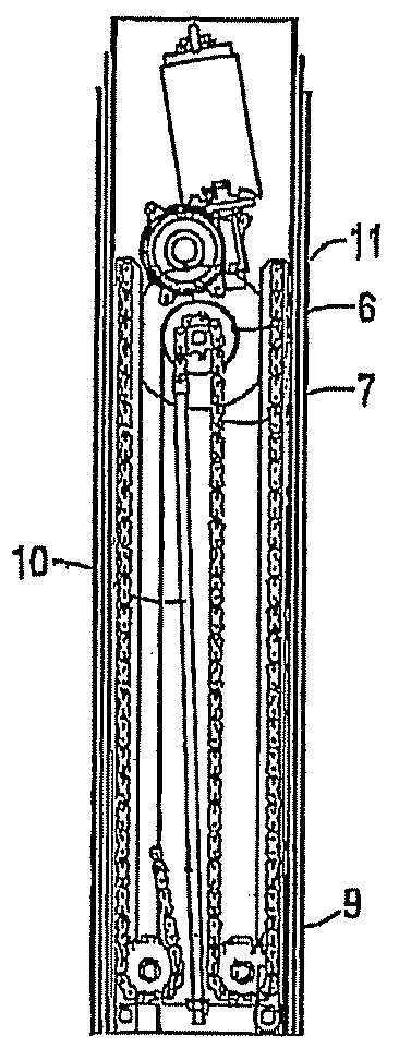
  • Drive for displacing profile parts relative to each other via a flexible material strip, length-adjustable housing and article of furniture
  • Drive for displacing profile parts relative to each other via a flexible material strip, length-adjustable housing and article of furniture
  • Drive for displacing profile parts relative to each other via a flexible material strip, length-adjustable housing and article of furniture

Examples


Embodiment Construction

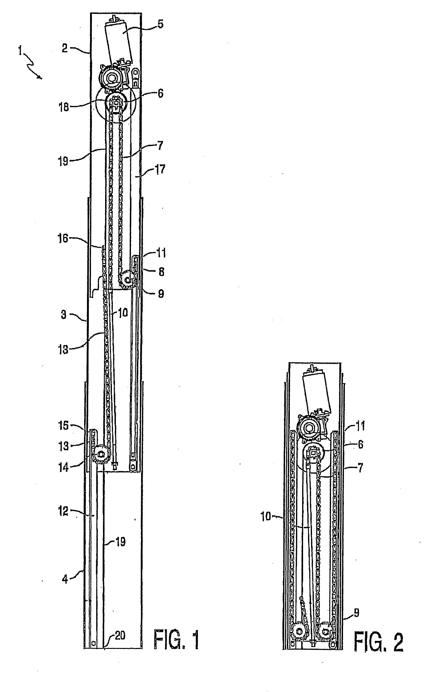
[0024]The present invention will now be described with reference to the accompanying figures. It is to be understood that the specific system illustrated in the attached figures and described in the following specification is simply an exemplary embodiment of the present invention.

[0025]FIG. 1 shows a leg 1 assembled from three telescopically co-acting profile parts 2, 3, 4. In a first profile part 2 is arranged an electric motor 5 to which is coupled a drive wheel 6 likewise connected to first profile part 2. Drive wheel 6 engages on a chain 7 which forms a flexible material strip with which the relative displacement of the first and second profile parts 2, 3 can be realized.

[0026]It should be realized that in stead of an electric motor 5 a drive shaft can be provided either for manual operation or operation through a further electric motor outside the leg of FIG. 1 for example an electric motor being in common for several legs.

[0027]On one side the chain 7 is connected to an uprig...


PUM


Abstract

A drive for displacing and positioning at least two profile parts relative to each other, includes: a rotatable drive wheel, a motor coupled to a first profile part and to the drive wheel, a flexible material strip which is rigidly connected on at least one side to a second profile part, which material strip also engages on the drive wheel, and a guide for the flexible material strip connected in at least substantially stationary manner to the first profile part, wherein the distance between the guide and the drive wheel is greater than the distance between the point of engagement of the flexible material strip on the second profile and the drive wheel. The invention also includes a length-adjustable housing provided with the aforementioned drive and to an article of furniture, in the legs of which such drives are accommodated.

Description

CROSS REFERENCE TO RELATED APPLICATIONS[0001]This application is a continuation-in-part application of U.S. patent application Ser. No. 10 / 518,978, filed Sep. 8, 2005, and entitled “Drive for Displacing Profile Parts Relative to Each Other Via a Flexible Material Strip, Length-Adjustable Housing and Article of Furniture,” the contents of which are incorporated herein by reference.BACKGROUND OF THE INVENTION[0002]1. Field of the Invention[0003]The invention relates to a drive for displacing and positioning at least two profile parts relative to each other. The invention also relates to a length-adjustable housing which is assembled from a plurality of relatively displaceable housing parts, and to an article of furniture of which such a housing forms part.[0004]2. Description of Related Art[0005]For the relative displacement of objects use is made in many applications of spindle / nut transmissions. A drawback of the existing systems is that generally they are relatively costly and heav...

Claims


Application Information

Patent Timeline
IPC IPC(8): F16M11/26A47B91/02A47B9/12A47B9/20
CPCA47B9/12A47B9/20Y10T74/1884F16H19/0663Y10T74/18848F16H19/06
Inventor STOELINGA, DIRK
Owner ACTIFORCE INT BV
Learn More