Fire detection

a fire detection and detection system technology, applied in the field of fire detection systems and methods, can solve problems such as the inability to indicate the likely location of fires

Inactive Publication Date: 2009-03-19
KIDDE IP HLDG
View PDF9 Cites 20 Cited by
  • Summary
  • Abstract
  • Description
  • Claims
  • Application Information

AI Technical Summary

Benefits of technology

[0018]There may be provided a reference fibre Bragg grating, which is maintained at a known temperature. This reference fibre Bragg grating is monitored to allow correction for drifting in the sensory equipment. It is possible to include more than one reference fibre Bragg grating covering a range of wavelengths to maintain the precision of measurement across the full wavelength range.

Problems solved by technology

A disadvantage of such smoke detection systems is that the location of the inlet through which the smoke particles were drawn cannot be readily determined, so the likely location of the fire cannot be indicated.
This approach is limited in that, although spatial and / or temperature variations in the locality of the fibre optic cable are detectable, there is no provision for the precise location of such variations, given that the resolution of the position information is practically only of the order of a few metres, meaning that only fibre Bragg gratings that are several metres apart can be distinguished.

Method used


Image

  • Fire detection
  • Fire detection
  • Fire detection

Examples


Embodiment Construction

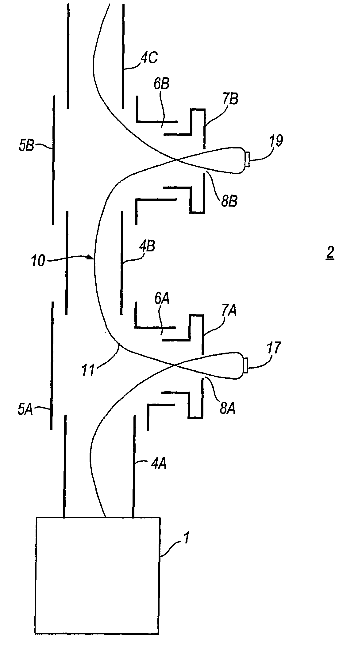
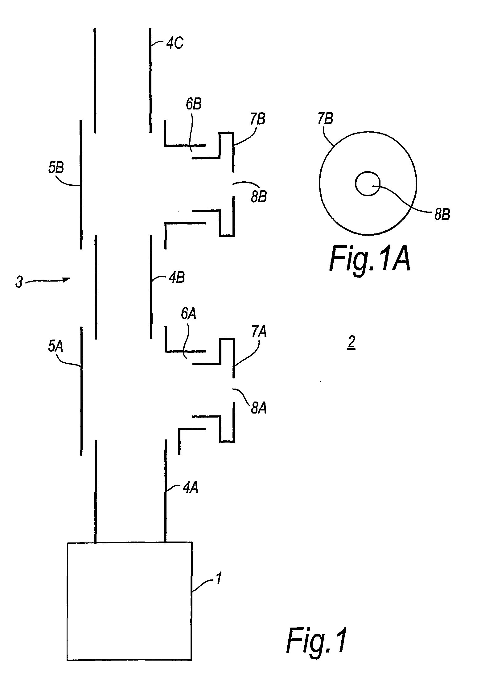
[0030]The smoke detection system of a generally known type shown in FIG. 1 comprises a smoke detector 1. For example, the smoke detector 1 may be a HART High Sensitivity Smoke Detection system available from Kidde Plc, which uses laser based technology to count particles of smoke in a gas for detecting a fire. The smoke detector 1 provides fire detection for a volume 2 containing air (although this could be some other fluid). A conduit 3 receives air from the volume 2. Typically, the volume 2 will be an enclosed space, such as a large warehouse storing electrical equipment or documents. Conduit 3 will be mounted near to the ceiling of the volume 2, and may comprise a plurality of connected pipes—for example, an array of pipes mounted on the ceiling or extending around the periphery of the ceiling. FIG. 1 shows one such pipe, comprising respective tubular pipe parts 4A,4B and 4C. Opposite ends of pipe parts 4A and 4B are coupled together by pipe coupling 5A. Pipe parts 4B and 4C are ...


PUM


Abstract

A fire detection system for monitoring a volume containing fluid, typically air, for the presence of smoke particles is disclosed. A conduit for receiving the fluid, and any smoke particles therein, and directing the fluid to a smoke detector has a plurality of inlets formed therein. A respective temperature sensor is associated with each of the inlets which generate a signal indicative of a change in temperature in the region of the inlet. In the embodiments, the temperature sensor comprises one or more fibre Bragg gratings. The fibre Bragg gratings preferably have different grating periods. The reflected light from each fibre Bragg grating is returned back down the fibre optic cable and redirected via a 2×1 coupler to a wavelength detection system and a personal computer. The combination of wavelength detection system and personal computer allow analysis of the reflected light patterns, as well as providing a user interface which enables detection of the occurrence of a spatial and/or a temperature variation. The location of the said variation along the fibre optic cable is advantageously detectable. The system described is highly sensitive to smoke, but can advantageously also provide an indication of the location of the smoke source, because any variation in temperature at any one of the smoke inlets is also detected, the location of the sensor being known.

Description

TECHNICAL FIELD[0001]This invention relates to a fire detection system and method.BACKGROUND ART[0002]Smoke detection systems are known that include a network of pipes with gas inlet ports / sampling points located at intervals around the network. Gas, and smoke particles, if present, enter into the network via the inlets, are drawn along the pipes, and can be detected by a suitable detector. For example, the HART High Sensitivity Smoke Detection system available from Kidde Plc is one such system, and comprises a laser-based aspirating detector which counts particles of smoke to reliably detect fire at its very earliest stages. A fan draws gas, and smoke particles if present, through the pipe network into the detector. A disadvantage of such smoke detection systems is that the location of the inlet through which the smoke particles were drawn cannot be readily determined, so the likely location of the fire cannot be indicated.[0003]The use of fibre Bragg gratings in sensors is well kn...

Claims


Application Information

Patent Timeline
Patent Type & Authority Applications(United States)
IPC IPC(8): G02B6/00G08B17/10G08B17/06
CPCG08B17/10G08B17/06G08B17/113G01K11/3206G08B17/00G01K11/32
Inventor POWELL, BRIAN DAVID
Owner KIDDE IP HLDG
Why Eureka
Try Eureka