Radar apparatus

a technology of radar and antenna, applied in the direction of multi-channel direction-finding systems using radio waves, instruments, measurement devices, etc., can solve the problems of difficult to detect the target peak, the antenna construction has to be changed, and the antenna cannot be detected. the effect of improving the detection performance of the target, high resolution and improving the gain of signals

Active Publication Date: 2009-03-19
MITSUBISHI ELECTRIC CORP
View PDF7 Cites 68 Cited by
  • Summary
  • Abstract
  • Description
  • Claims
  • Application Information

AI Technical Summary

Benefits of technology

[0017]Another object of the present invention is to obtain a radar apparatus which is capable of achieving high resolution without changing antenna construction, and in which the calculation load is small.
[0019]According to the present invention, as a method for calculating the direction of a target, there is employed super-resolution direction-of-arrival estimation processing instead of DBF synthetic processing, so it is possible to obtain a high degree of resolution without changing antenna construction.
[0020]In addition, in case where the RCS of a target is small (or a target is at a distance), even if a peak of a beat frequency spectrum resulting from a target is buried in the beat frequency spectrum before the channel to channel integration thereof, it is possible to improve the gain of signals by executing channel to channel integration over the entire range of the frequencies of the beat frequency spectrum. Accordingly, the detection performance of the target can be improved, thus making it possible to detect a peak beat frequency in a correct manner.
[0021]Further, in the beat frequency spectrum before the channel to channel integration thereof, the direction of the target is obtained by calculating the angular spectrum only for the peak beat frequency resulting from the target, so it is possible to decrease the calculation load in comparison with the case in which the direction of the target is obtained by calculating the angular spectrum over the entire frequency range.

Problems solved by technology

In the beat frequency spectrum before the DBF synthetic processing in the conventional radar apparatus, there has been a problem that when the RCS (Radar Cross Section) of a target is small or a target is at a distance, it becomes difficult to detect a peak resulting from the target.
More specifically, according to the method of performing the DBF synthetic processing only on the frequencies, of which the amplitude is greater than the predetermined value, in the beat frequency spectrum obtained by applying the frequency analysis to the received signals, as in the first patent document, there has been a problem that if the RCS of a target is small or a target is far away, it might be impossible to detect the target.
In addition, in the technique for calculating the direction of the target by using the DBF synthetic processing, as in the first patent document, there is also a problem that the construction of the antenna has to be changed in order to obtain a high degree of resolution.
As a result, there is a problem that the huge amount of calculations is necessary as compared with the case in which only an angular spectrum of limited frequencies is calculated, thus resulting in a substantial increase in the calculation load.

Method used


Image

  • Radar apparatus
  • Radar apparatus
  • Radar apparatus

Examples


embodiment 1

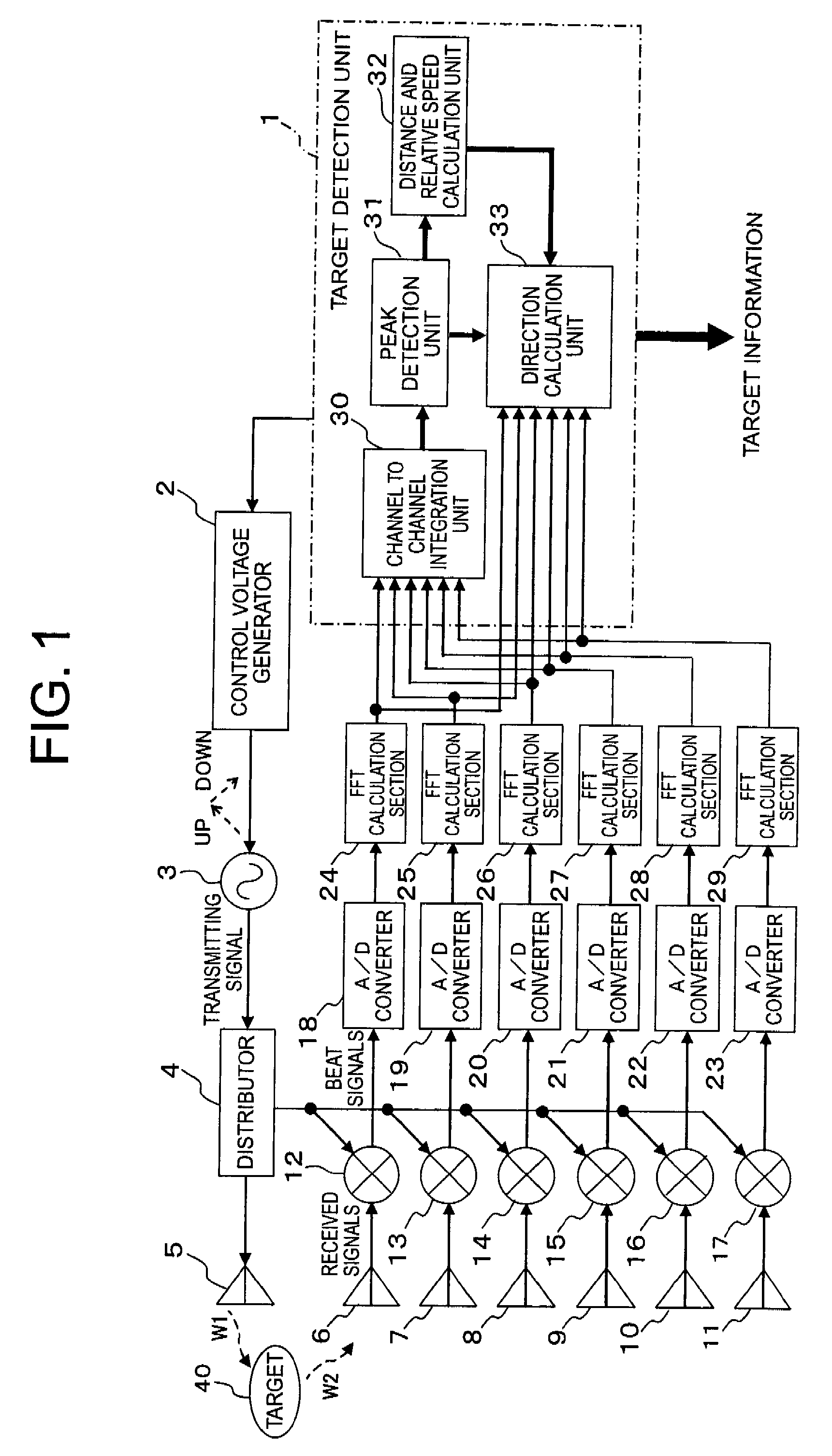
[0034]Referring to the drawings and first to FIG. 1, there is shown, in a block diagram, a radar apparatus according to a first embodiment of the present invention.

[0035]In FIG. 1, the radar apparatus includes a target detection unit 1 in the form of a microcomputer, a control voltage generator 2 that outputs a control voltage under the control of the target detection unit 1, a VCO (Voltage Controlled Oscillator) 3 that outputs a transmitting signal with its frequency up / down modulated based on the control voltage, a distributor 4 that distributes a transmitting signal, and a transmitting antenna 5 (transmitting unit) that emits a transmitting signal W1 to a target 40 which may comprise a single target component or a plurality of target components.

[0036]In addition, the radar apparatus further includes a plurality of receiving antennas 6 through 11 (receiving unit) in the form of an array having a plurality of channels (e.g., 6 channels) for receiving a reflection signal W2 which is...

embodiment 2

[0082]In the above-mentioned first embodiment (FIG. 1), the frequency analysis results from the FFT calculators 24 through 29 are directly input to the channel to channel integration unit 30 in the target detection unit 1, they may be input to a sweep to sweep integration processing unit 30 between sweeps as shown in FIG. 5 after through a sweep to sweep integration unit 34.

[0083]FIG. 5 is a block diagram that shows a target detection unit 1A of a radar apparatus according to a second embodiment of the present invention, which is the same in construction as that in the above-mentioned (FIG. 1) except for the additional provision of the sweep to sweep integration unit 34. In addition, the construction of peripheral circuits and the like (not shown) is the same as shown in FIG. 1.

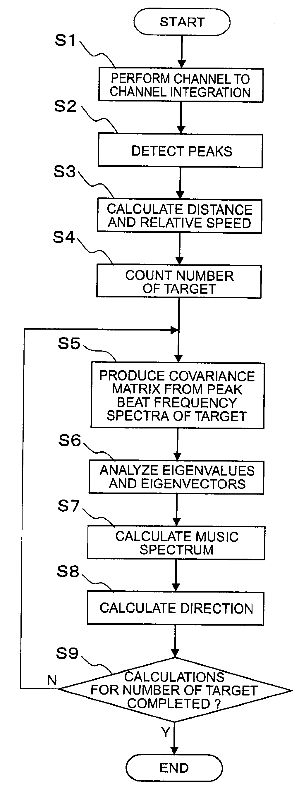
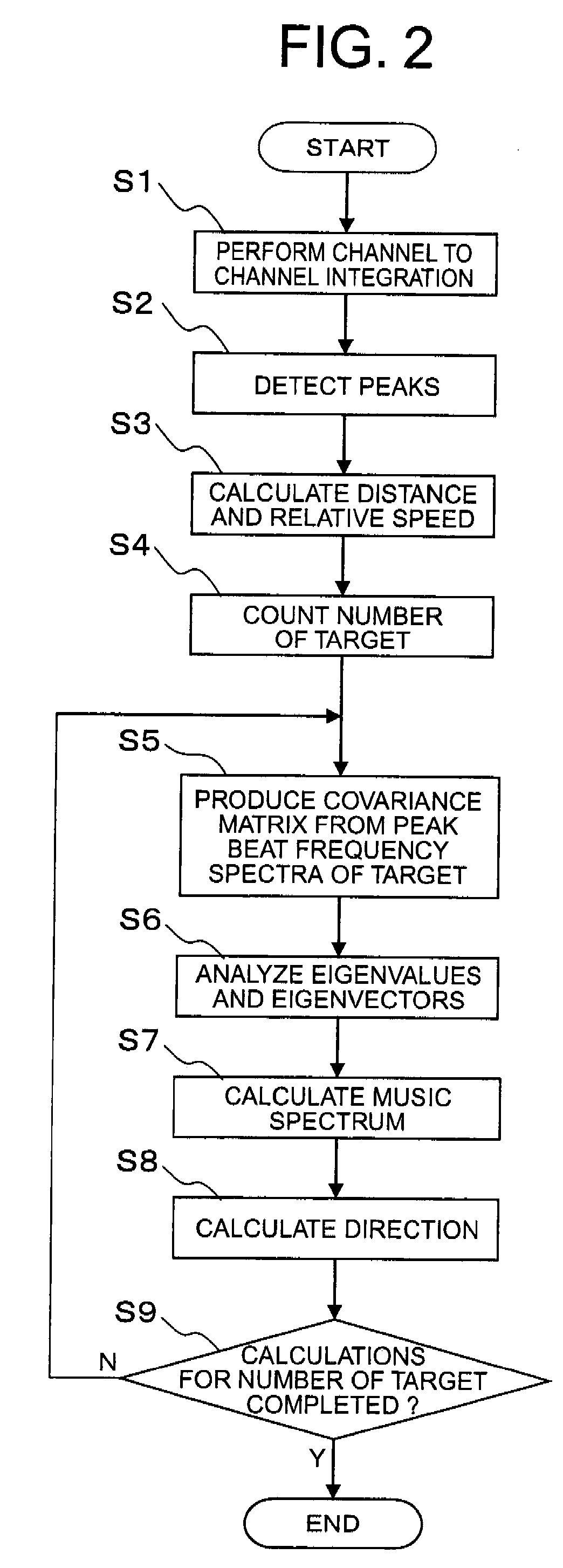
[0084]Now, reference will be made to the operation of the target detection unit 1A according to the second embodiment of the present invention as illustrated in FIG. 5 while referring to a flow chart of FIG. ...

embodiment 3

[0099]Although in the above-mentioned second embodiment (FIG. 5), the sweep to sweep integration unit 34 is inserted at an input side of the channel to channel integration unit 30, it may be inserted at an output side of the channel to channel integration unit 30, so that there is provided the processing of adding, for each of the same beams and at each of the same frequencies, the amplitudes or the electric powers of the beat frequency spectra calculated in a plurality of time ranges after the processing of the channel to channel integration unit 30.

[0100]Hereinafter, reference will be made to a radar apparatus according to a third embodiment of the present invention while referring to an explanatory view in FIG. 4 together with FIG. 8. Here, note that the basic construction of the radar apparatus according to the third embodiment of the present invention is as shown in FIG. 1, and the block construction of a target detection unit 1A is such that the channel to channel integration ...


PUM


Abstract

A radar apparatus can improve detection performance of a target, obtain high resolution without changing antenna construction, and suppress calculation load. A target detection unit, which calculates a distance, a relative speed, or a direction of the target based on frequency analysis results for a plurality of channels, includes a channel to channel integration unit that integrates, for each of the same frequencies, beat frequency spectra for the plurality of channels in the form of frequency analysis results for beat signals obtained for each of a plurality of receiving antennas, and a direction calculation unit that calculates the direction of the target from the beat frequency spectra for the plurality of channels.

Description

BACKGROUND OF THE INVENTION[0001]1. Field of the Invention[0002]The present invention relates to a radar apparatus that calculates target information based on a reflection signal which is reflected from an object to be detected (hereinafter referred to as a “target”) and which is received by a plurality of receiving elements when a transmitting signal (radio wave) is radiated to the target.[0003]2. Description of the Related Art[0004]Conventionally, as a radar apparatus capable of calculating a distance and a relative speed to a target, there has been known a frequency modulation radar apparatus that sends a transmitting signal with its frequency modulated to the target in a continuous or successive manner, receives a reflection signal from the target, and calculates the distance and the relative speed with respect to the target based on the reflection signal thus received.[0005]As a target direction calculation method in such a kind of radar apparatus, there has been known a method...

Claims


Application Information

Patent Timeline
Patent Type & Authority Applications(United States)
IPC IPC(8): G01S13/58G01S13/04
CPCG01S3/74G01S2013/0263G01S13/584G01S13/345
Inventor NAKAGAWA, KADO
Owner MITSUBISHI ELECTRIC CORP
Why Eureka
Try Eureka