Image processing apparatus and image processing method

a technology of image processing and image processing apparatus, which is applied in the field of image processing apparatus and image processing method, can solve the problems of small large amount of motion blur, and rare motion blur in pursuit, and achieve the effect of suppressing the accumulation of electrical charges

Inactive Publication Date: 2009-03-19
CANON KK
View PDF11 Cites 46 Cited by
  • Summary
  • Abstract
  • Description
  • Claims
  • Application Information

AI Technical Summary

Problems solved by technology

However, the motion blur in pursuit is rarely observed.
Longer periods of light emission result in larger amounts of motion blur.
Shorter periods of light emission result in smaller amounts of motion blur.
On the other hand, concerning flicker synchronous with a frame, longer periods of light emission result in smaller flicker.
Shorter periods of light emission result in larger flicker.
As described above, multiplying the frame frequency by N has a large effect but poses a new problem.
This solves flicker but cannot improve the motion blur in the original picture.
In the first method, the amount of calculation is enormous, and a prediction error occurs under a specific condition.
In a display using a liquid crystal panel, if the liquid crystal panel is driven while the DC balance is disturbed, electrical charges are accumulated between electrodes to degrade the image quality.
However, even if signals are identical, the display sensitivity or non-linear characteristic to the drive voltage is not always the same or symmetrical between a case where the device is driven by a positive voltage and a case where it is driven by a negative voltage.
The luminance slightly changes between these two cases, causing flicker.
This pixel inversion or line inversion causes the following problems in a method of performing projection display using a microdisplay, like a rear projector or front projector.
That is, the electric field leaks between inverted areas (so-called disclination), adversely affecting the display picture.
If the polarity is inverted in a long cycle, changes of the luminance and color stand out, degrading the image quality.

Method used


Image

  • Image processing apparatus and image processing method
  • Image processing apparatus and image processing method
  • Image processing apparatus and image processing method

Examples


first embodiment

Outline of Operation

[0043]An outline of the first embodiment according to the present invention will be explained. The first embodiment proposes an improvement in the “sub-frame display method based on spatial frequency separation”.

[0044]An image display apparatus which displays display image data generated by an image processing apparatus according to the first embodiment implements the “sub-frame display method based on spatial frequency separation”. More specifically, the image display apparatus displays a picture by driving one by one the display elements of a liquid crystal panel having counter electrodes. The image display apparatus separates one frame of a moving picture into a plurality of sub-frames, and executes frame inversion type AC driving to invert the drive polarity for each sub-frame.

[0045]The image display apparatus according to the first embodiment displays a picture signal having a frame rate of 60 Hz at a display refresh rate of 120 Hz. That is, the image proces...

second embodiment

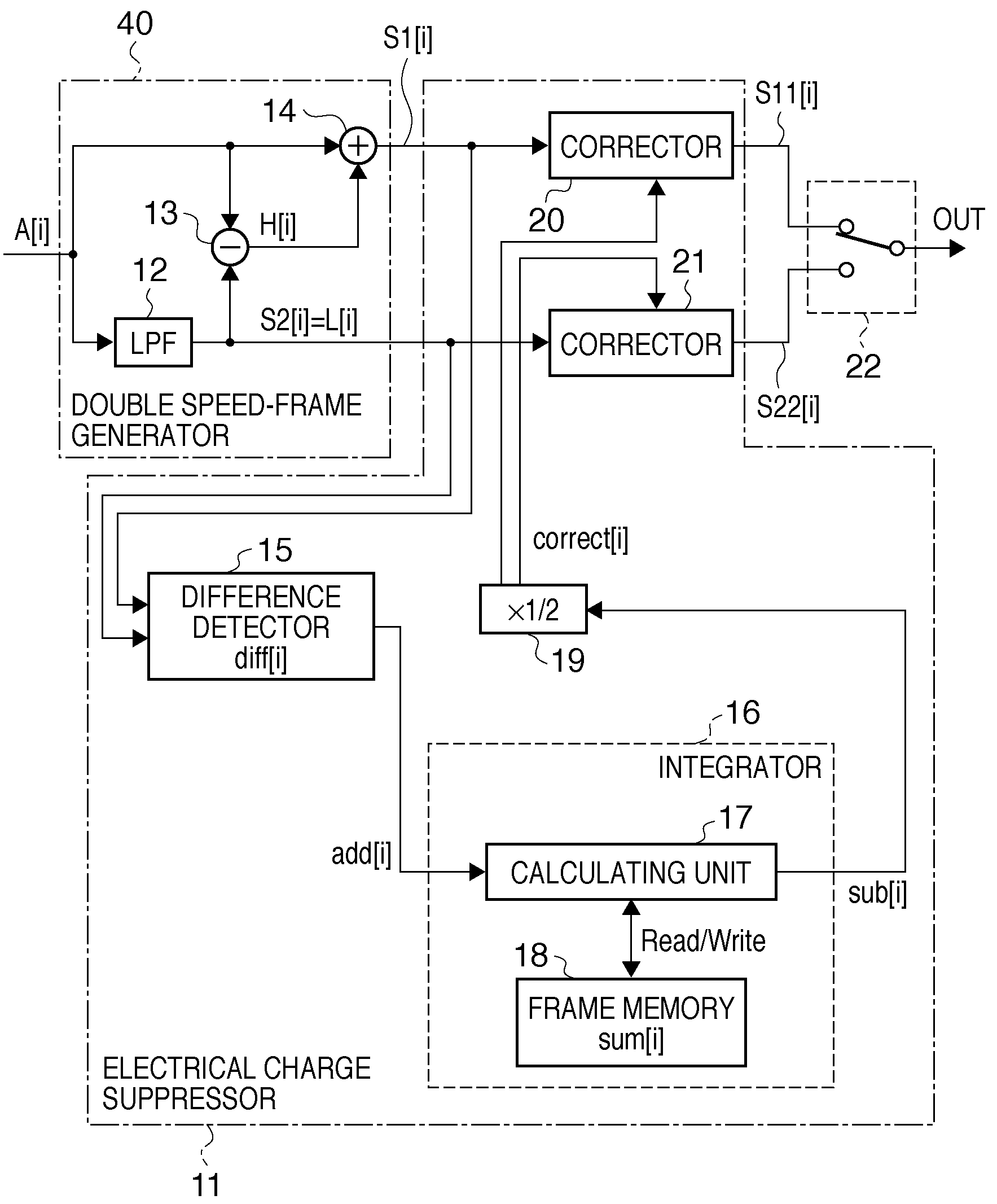
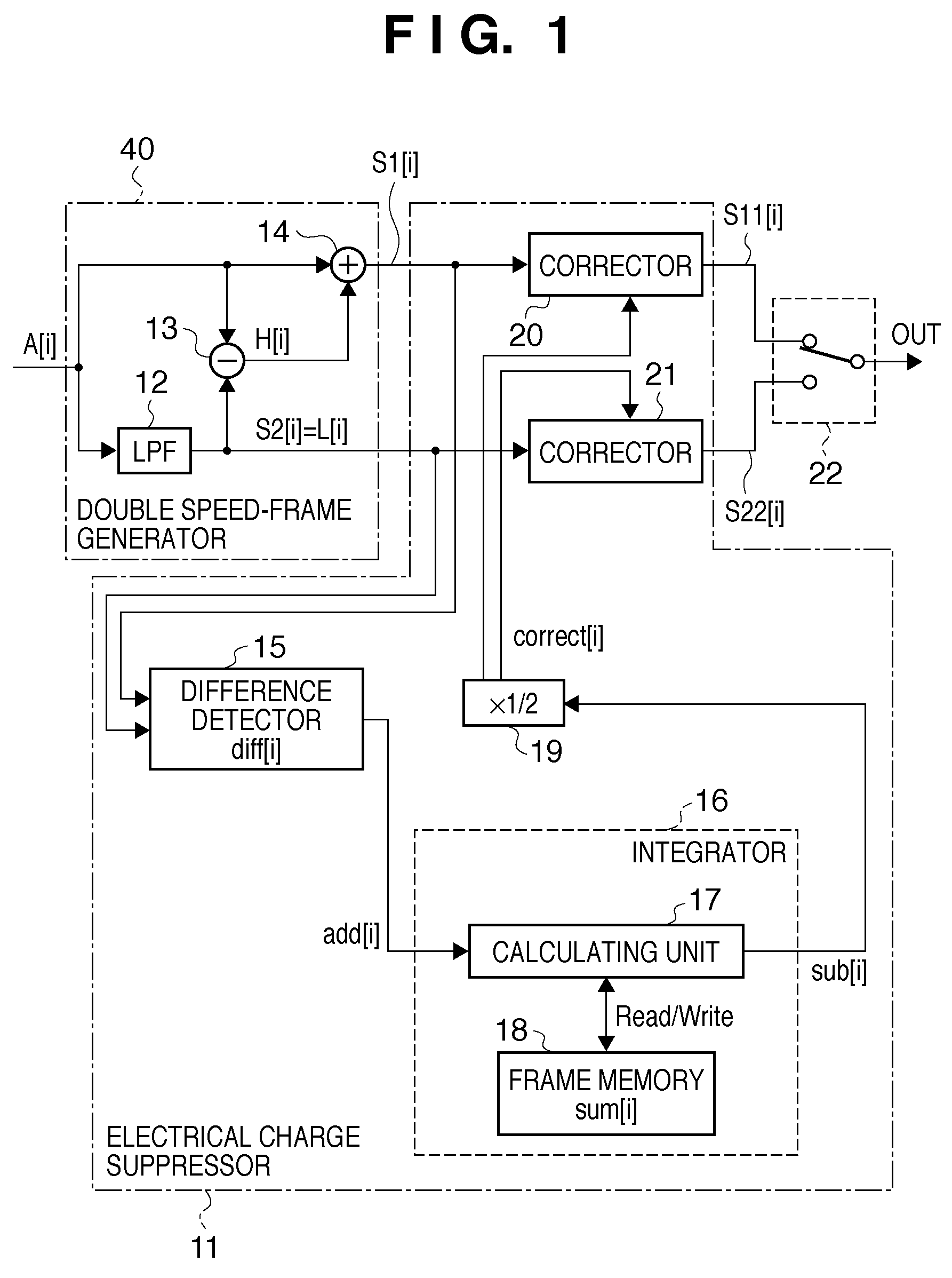
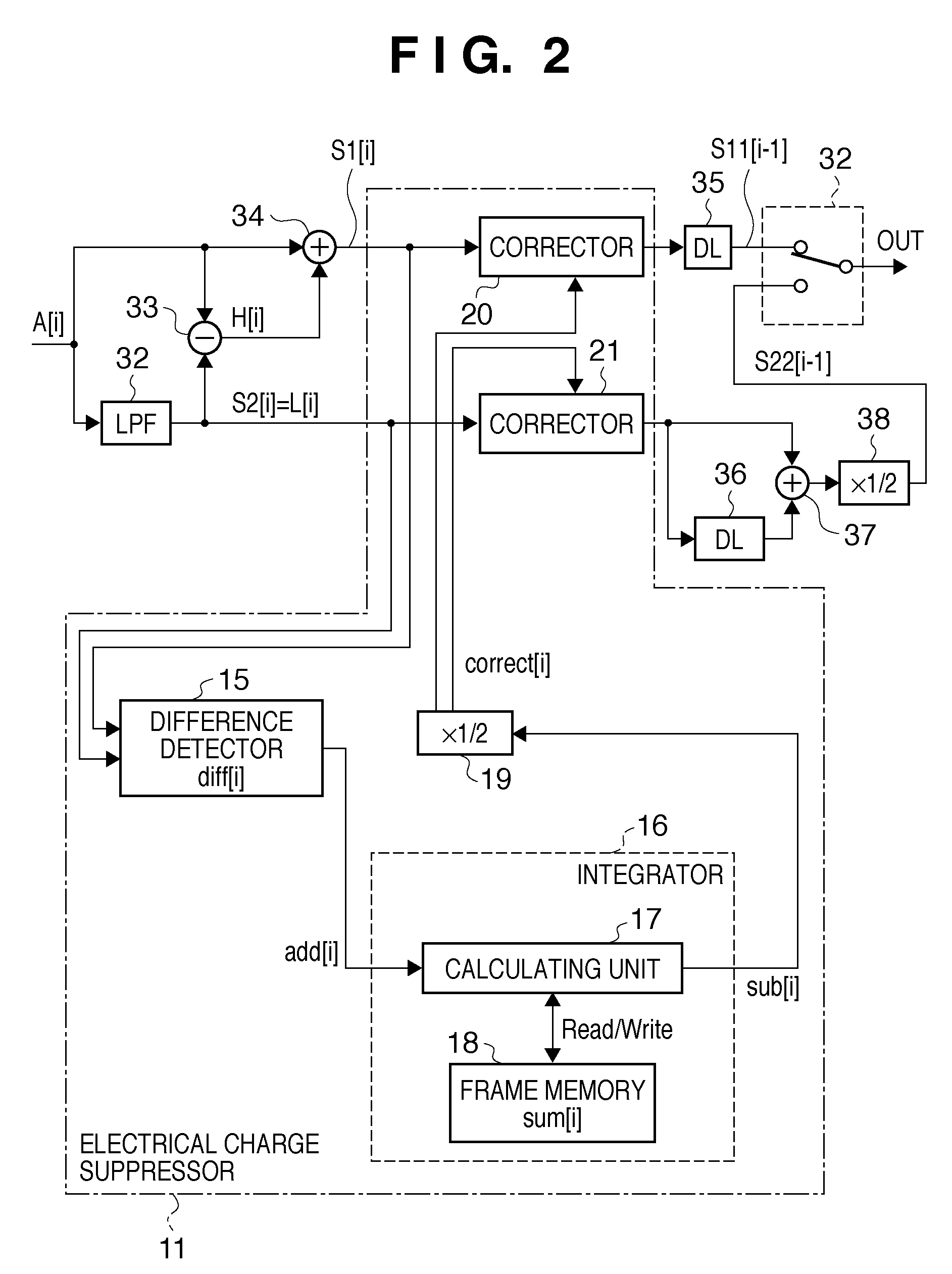
[0098]The second embodiment according to the present invention will be described. The second embodiment will explain electrical charge accumulation control capable of more preferable moving picture playback.

[0099]The present applicant has proposed a technique which improves the conventional “sub-frame display method based on spatial frequency separation” shown in FIG. 17. FIG. 18 is a block diagram showing the arrangement of an image processing apparatus proposed by the present applicant for implementing the “sub-frame display method based on spatial frequency separation”.

[0100]In the arrangement shown in FIG. 17, the center of gravity of the luminance area changes in the time direction between the display of the high frequency component H[i] and that of the low frequency component L[i], as shown in FIG. 4A. This causes an asymmetrical distortion (so-called tailing-blur) in a direction in which a pursued object moves, and an opposite direction. In the arrangement shown in FIG. 18, g...

third embodiment

[0108]The third embodiment according to the present invention will be described. The third embodiment will explain an example of inverting a double speed-frame generated by the “intermediate picture insertion method based on motion compensation” serving as the first method of doubling the frame speed, and displaying the inverted frame on a microdisplay.

[0109]FIG. 11 is a block diagram showing the arrangement of an image processing apparatus which implements the “sub-frame display method based on spatial frequency separation” according to the third embodiment. In FIG. 11, a double speed-frame generator 30 generates a double speed-picture by the “intermediate picture insertion method based on motion compensation”. As the double speed-picture in the third embodiment, an input picture A[i] is displayed every other sub-frame, and an intermediate picture Sm[i] calculated by motion compensation is displayed between input pictures A[i]. In the third embodiment, the difference (addition valu...


PUM

PropertyMeasurementUnit
frequencyaaaaaaaaaa
frame frequencyaaaaaaaaaa
frequencyaaaaaaaaaa

Abstract

In an image display apparatus which displays a picture by inverting the drive polarity for each sub-frame, when the pictures of adjacent sub-frames are different from each other, image data is generated to prevent accumulation of electrical charges in each display element. For this purpose, the first and second sub-frames are generated from a frame of interest of a moving picture. The difference between the pictures of the first and the second sub-frames is detected. A correction value is calculated by subtracting from the difference a cumulative value multiplied by a predetermined coefficient. A value obtained by subtracting the correction value from the difference is accumulated as the cumulative value. The pictures of the first and second sub-frames are corrected by the correction value.

Description

BACKGROUND OF THE INVENTION[0001]1. Field of the Invention[0002]The present invention relates to an image processing apparatus and image processing method for generating image data to be supplied to an image display apparatus which inverts the drive polarity of display elements in each of plural sub-frames formed from a frame of a moving picture to display the moving picture.[0003]2. Description of the Related Art[0004]A cathode ray tube (CRT) has been synonymous with a moving picture display device for a television and the like. However, liquid crystal displays (LCDs), plasma displays (PDPs), and field emission displays (FEDs) have been put into practical use in recent years. There are displays of various display types now. The displays of these types adopt different display methods. For example, display devices based on a liquid crystal display (e.g., a direct viewing type LCD, liquid crystal rear projector, and liquid crystal front projector) use many scanning methods. In any cas...

Claims


Application Information

Patent Timeline
Patent Type & Authority Applications(United States)
IPC IPC(8): G09G5/00G02F1/133G09G3/20G09G3/36H04N7/01
CPCG09G3/2022G09G3/3614G09G2320/0247G09G2320/0261H04N7/0127G09G2340/16H04N5/144H04N5/208G09G2340/0435
Inventor KOBAYASHI, KIWAMU
Owner CANON KK
Why Eureka
Try Eureka