Device intended to support the driving of a motor vehicle comprising a system capable of capturing stereoscopic images

a technology of stereoscopic images and support systems, applied in the field of advanced driving support systems, can solve the problems of not offering a wide range of vision, not providing any information on the highway environment, and their angular positioning is never very precise, so as to reduce the amount of space required at the windscreen level, simplify the driving support system, and integrate the different items of equipment.

Active Publication Date: 2009-03-19
VALEO VISION SA
View PDF16 Cites 27 Cited by
  • Summary
  • Abstract
  • Description
  • Claims
  • Application Information

AI Technical Summary

Benefits of technology

[0016]The subject of the present invention proposes a solution to the problems raised above. The invention still proposes the use of a stereoscopic system for the capture of images contained within a device intended to support driving, but it proposes that the system be carried out in such a way that it offers and make possible a genuine multifunctionality in terms of driving support applications. The introduction of the aspect of multifunctionality is accompanied by a number of advantages, for example the integration of the different items of equipment required for the driving support systems is simplified, the amount of space required at a windscreen level is reduced and both the cost and the complexity of the linkages are reduced. To this end, the present invention proposes that the device intended to support driving a motor vehicle employs a stereoscopic system comprising two cameras having different fields of vision, thereby incorporating the advantages of both image capturing systems. Preferably, this would comprise both a grey levels camera and a color camera, thus allowing more functions to be employed.
[0019]In this way, the second camera is able to capture an image on a zone equivalent to a part of the image captured by the first camera, enabling a zoom effect to be created in the second image.
[0027]In the same way as the RGB type sensors, sensors of the RGBi types and sensors of the RedClear type function by using a grey levels sensor in front of which is arranged a filter. In the case of the RGBi sensors, this filter enables the red, green, blue and infra-red components of the captured image to be calculated, while in the case of the RedClear sensor, the capture of the grey levels images is associated with the calculation of the red components of the captured image. The advantage of the RedClear sensors is that they provide important color information (e.g. red tail lights) and furthermore their resolution is better than that of an RGB or an RGBi sensor.

Problems solved by technology

But sensors of this type do not offer a wide range of vision and their angular positioning is never very precise.
Moreover, they do not provide any information on the highway environment, such as the position of the vehicle within its traffic lane, the number of traffic lanes, the trajectory of the route, the classification of the obstacles, the possibility of recognizing infrastructural elements such as roadside panels, etc.
Moreover, long range, narrow fields are unable to detect at a sufficiently early stage so-called > scenarios, where a vehicle arriving from a different traffic lane to that of the vehicle fitted with the sensor threatens to > and the driver has to be responsible for controlling the situation.
However, these filters have the effect of reducing the spatial resolution of the sensor device used with the result that the calculation of the distance—often effected by measuring the distance between two projectors and a detected vehicle—obtained by the use of a single color sensor is less precise than a calculation carried out by a single grey levels sensor.
However, above a certain distance, a grey levels sensor cannot enable the tail lamps of one vehicle to be distinguished from those of another and as it does not receive any color information it cannot enable tail lamps to be detected at all.
But the presence of two cameras for a dedicated function represents a major cost item, with the result that this solution is often prohibitive.

Method used


Image

  • Device intended to support the driving of a motor vehicle comprising a system capable of capturing stereoscopic images
  • Device intended to support the driving of a motor vehicle comprising a system capable of capturing stereoscopic images

Examples


Embodiment Construction

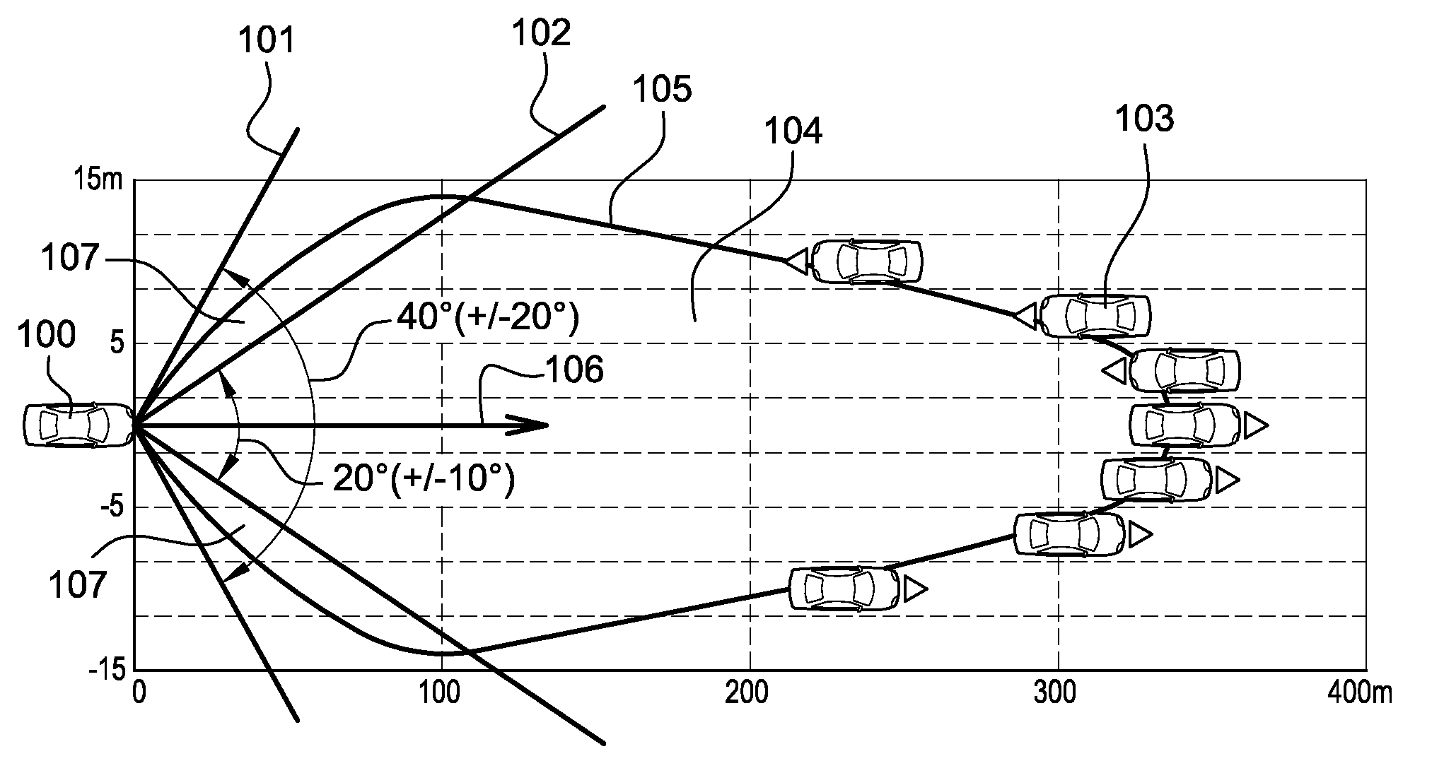
[0042]FIG. 1 shows a vehicle 100 fitted with a device according to the present invention. This latter comprises at least a first camera of the grey levels camera type, which does not therefore provide color information, and a second camera of the color camera type. In the example shown, the first camera has a first field of vision 101, defined by a viewing angle centered on the direction of travel 106 of the vehicle 100, the size of this angle being in the order of 40 degrees. The second camera has a second field of vision 102, also centered on the direction of travel 106 of the vehicle 100, with a lesser field of vision than the first camera, for example in the order of 20 degrees. Advantageously, the second field of vision 102 contains a complete glare zone 105, representing a zone, in which any other vehicle 103 that is present risks being dazzled if the vehicle 100 uses its main beam headlamps. In this way, the two zones present an overlapping or covering zone 104, for which the...


PUM


Abstract

A system and method to support the driving of a motor vehicle comprising in particular a system capable of capturing images, wherein the system for capturing images comprises a stereoscopic image capturing system having at least a first camera and a second camera, with the first camera presenting a field of vision) greater than the field of vision of the second camera, and with the stereoscopic system thereby conferring a degree of multifunctionality to the device supporting the driving of the vehicle.

Description

CROSS-REFERENCE TO RELATED APPLICATIONS[0001]This application claims priority to French Application No. 0706533 filed Sep. 17, 2007, which application is incorporated herein by reference and made a part hereof.BACKGROUND OF THE INVENTION[0002]1. Field of the Invention[0003]Generally speaking, the sphere of application of the present invention is that of advanced driving support systems, and more particularly, of that of the detection and identification of obstacles, in particular other vehicles either crossing the vehicle's path or travelling in front of it.[0004]2. Description of the Related Art[0005]The detection and identification of obstacles is one of the most researched and key spheres in the field of research into advanced driving support systems introduced during the last fifteen years, in particular by manufacturers of motor vehicles and motor vehicle equipment. Numerous solutions have been envisaged and put into practice for the detection and identification of obstacles fr...

Claims


Application Information

Patent Timeline
Patent Type & Authority Applications(United States)
IPC IPC(8): H04N13/02H04N7/18
CPCB60W30/08B60W40/02G06T2207/30252G06T7/0022H04N13/025B60W2420/403G06T7/97H04N13/25
Inventor ROBERT, CAROLINEREBUT, JULIEN
Owner VALEO VISION SA
Why Eureka
Try Eureka