

Image processing apparatus, image processing method, and computer-readable recording medium
a technology of image processing and recording medium, applied in the field of image processing technique, can solve the problems of loss of information at edges of output image, above-described marginless copy and marginless printing operations, and output image undetectedly becoming larger, so as to reduce the loss of information at edges
- Summary
- Abstract
- Description
- Claims
- Application Information
AI Technical Summary
Benefits of technology
Problems solved by technology
Method used
Image

Examples
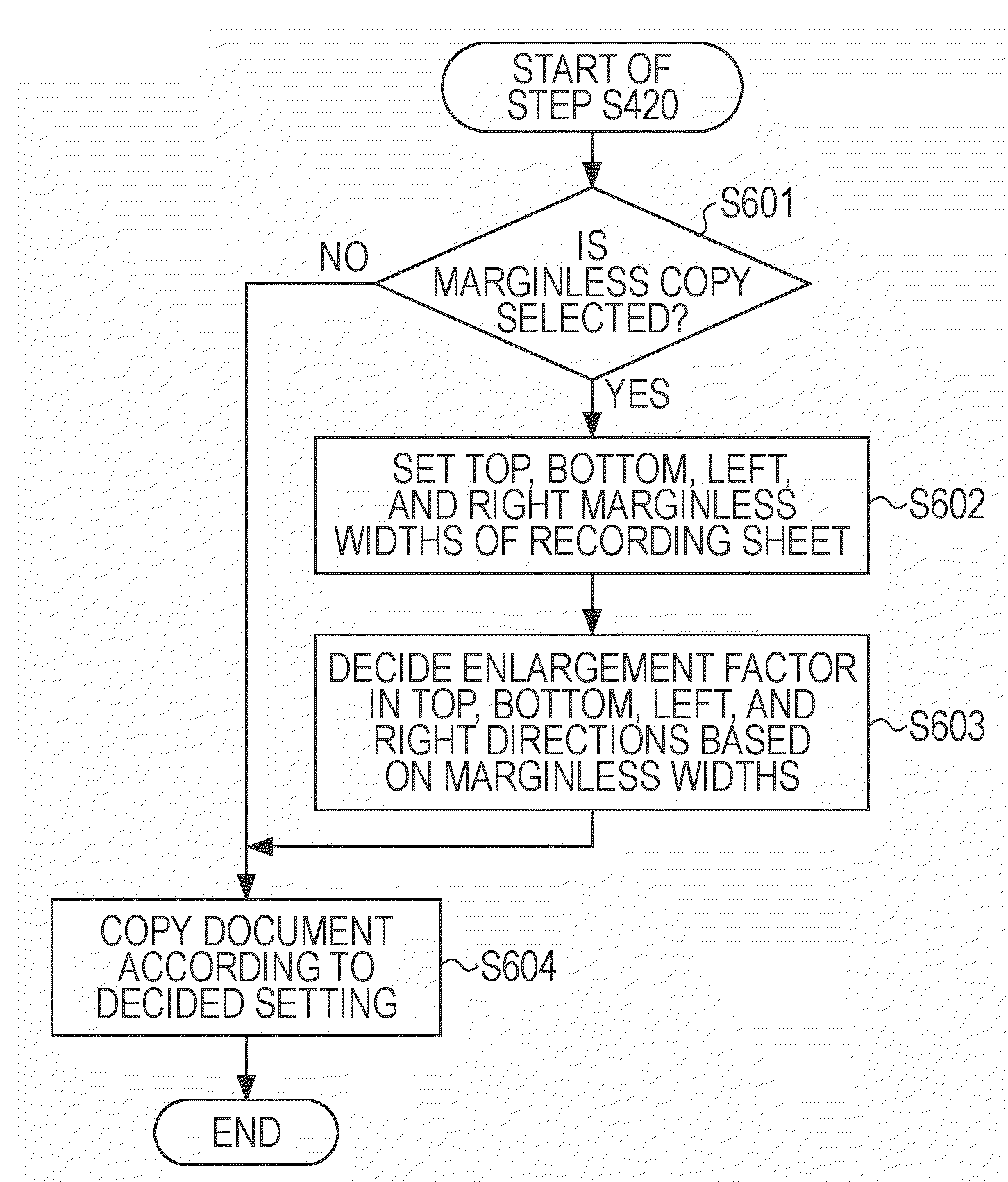
first exemplary embodiment
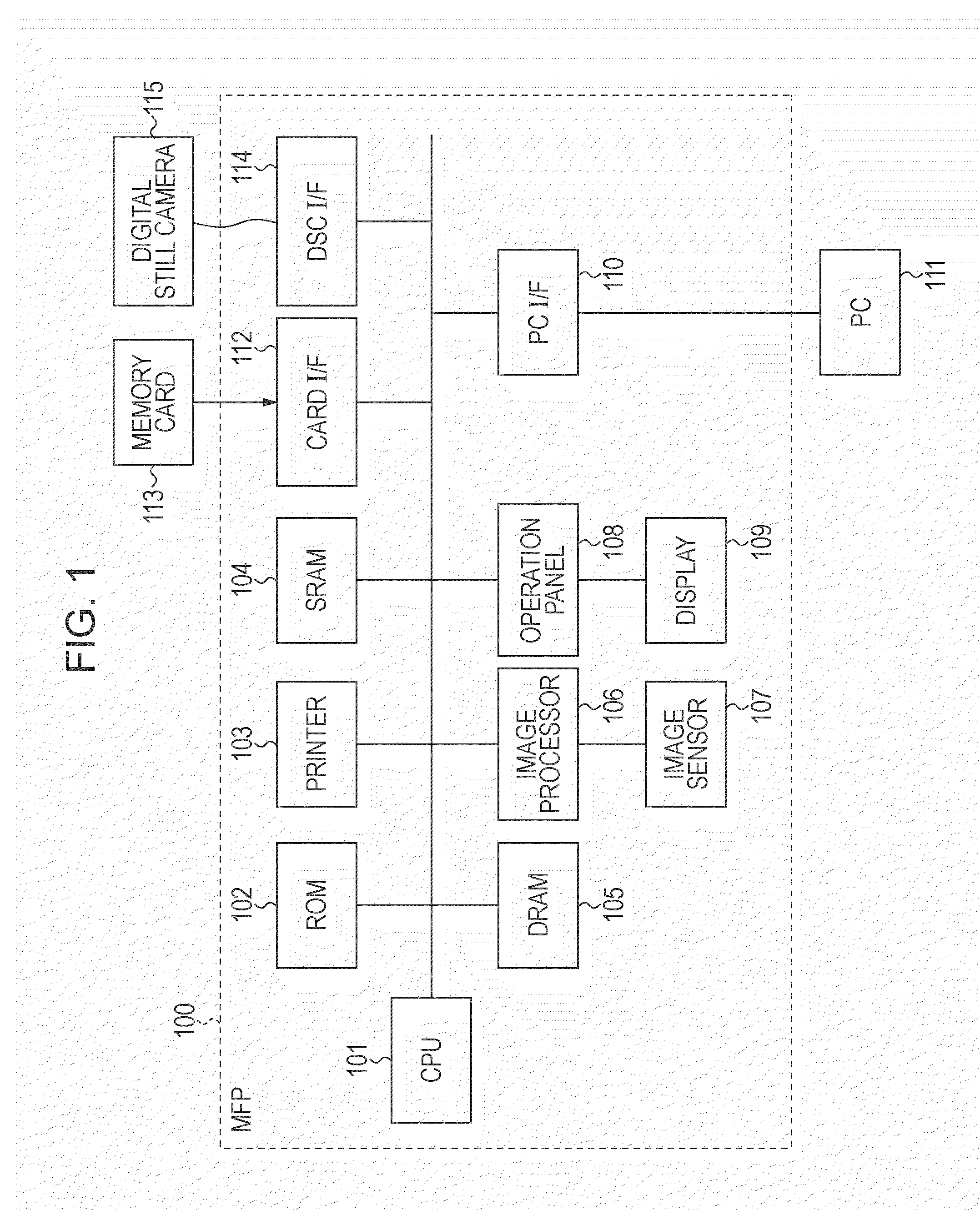
1. System Configuration of Image Processing Apparatus
[0058]FIG. 1 illustrates a system configuration of an image processing apparatus (an MFP 100) according to a first exemplary embodiment of the present invention. Referring to FIG. 1, a central processing unit (CPU) 101 serves as a system control unit of the MFP 100 and controls each block constituting the MFP 100.
[0059]A read-only memory (ROM) 102 stores system control programs of the MFP 100. The CPU 101 executes various kinds of processing regarding the MFP 100 on the basis of the control programs stored in the ROM 102. Such control programs executed by the CPU 101 may be stored in an external storage medium, such as a flexible disk or a CD-ROM, in addition to the ROM 102. In addition, the control programs may be loaded to a random access memory (RAM), for example, an SRAM 104, of the MFP 100 by a dedicated reader, and decoded and executed by the CPU 101.
[0060]A printer 103 has a function for recording scanned or input image dat...
second exemplary embodiment
[0172]In the first exemplary embodiment, the description has been given for a case where enlargement factors are set in respective directions from a center of an original image. However, when enlargement factors based on marginless widths are set in top, bottom, left, and right directions as in the case of the first exemplary embodiment, the entire image may be distorted since the enlargement factors differ in each direction from the center of the original image.
[0173]Additionally, there is no difference in the image loss ratio between a method according to the first exemplary embodiment and a method for setting the center of the original image not to match the center of the original image formed on the recording sheet using an MFP according to related art.
[0174]Accordingly, in this exemplary embodiment, a description will be given for a case of further reducing an image loss ratio while avoiding occurrence of distortion of an image by providing a non-marginless enlarged area.
[0175]...
third exemplary embodiment
[0199]In the above-described second exemplary embodiment, the description has been given for a marginless copy operation when a marginless enlarged area having widths equal to marginless widths is set. However, the present invention is not limited to such a setting.
[0200]A description will be given below for an image loss ratio obtained when a smallest width of top, bottom, left, and right marginless widths is set as the width of a marginless enlarged area with reference to FIGS. 10B and 11B.
[0201]FIG. 10B shows layout of a document and a recording area when the smallest width of top, bottom, right, and left marginless widths is set as the width of an marginless enlarged area. FIG. 11B shows an image loss ratio resulting from calculation performed on the layout shown in FIG. 10B.
[0202]Referring to FIG. 10B showing an example layout employed in the MFP 100 according to the exemplary embodiment, a thick solid line 1000b shows a size of a document, whereas a thick broken line 1001b sho...
PUM
 Abstract
Description
Claims
Application Information