Road-terrain detection method and system for driver assistance systems

a detection method and a technology for driving assistance, applied in the field of driver assistance, can solve the problems of insufficient state of the art approaches based on the detection of delimiting elements of lane/road, inability to compensate for errors, and restricted to very specific settings. the effect of local properties

Active Publication Date: 2016-09-06
HONDA RES INST EUROPE
View PDF36 Cites 5 Cited by
  • Summary
  • Abstract
  • Description
  • Claims
  • Application Information

AI Technical Summary

Benefits of technology

[0050]As mentioned above, such a two-step process of property extraction and spatial feature generation before performing a classification is superior to the existing prior art, because the information loss can be reduced.
[0051]Preferably, the at least one sensor is one or more cameras, radars, laser scanners or GPS\navigation systems. A fusing of different sensors signals from different sensors can lead to an increased reliability of the detection results.
[0054]Preferably, the method comprises a step of sensory preprocessing for all sensor signals to obtain a common representation of the environment, wherein the sensory preprocessing is preferably an inverse perspective mapping of a camera image to get a metric image representation. The efficiency and reliability of the detection results can be increased with the preprocessing.
[0069]Automatic parameter determination and application of the principle of machine learning enabling the system to capture a wide variety of driving environments in real world.

Problems solved by technology

However, such detection methods require a depth sensor and are restricted to very specific settings, like e.g. a clearly visible curbstone in a short distance.
However, a detection that is based only on such delimiting elements of the lane / road can be erroneous, because the lane markings and curbstones are sometimes hard to detect.
This is an example where the state of the art approaches that are solely based on the detection of delimiting elements are insufficient.
Another disadvantage of the above-described prior art is the use of a decision process on sensor data, in order to infer directly the existence of delimiting elements and / or road surface properties.
A further disadvantage of the state of the art systems and methods is that the parameters for road detection are usually hand-coded.
Hand-coding is a time-consuming and error-prone process.
Furthermore, hand-coding prohibits the handling of more complex scenarios, since a large variability is difficult to hand-code.
For example, a pot hole in the road could cause a wrong decision that the corresponding road region is non-drivable based on local properties.

Method used


Image

  • Road-terrain detection method and system for driver assistance systems
  • Road-terrain detection method and system for driver assistance systems
  • Road-terrain detection method and system for driver assistance systems

Examples


Embodiment Construction

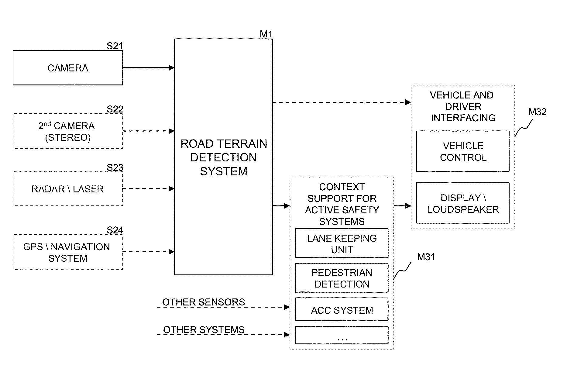
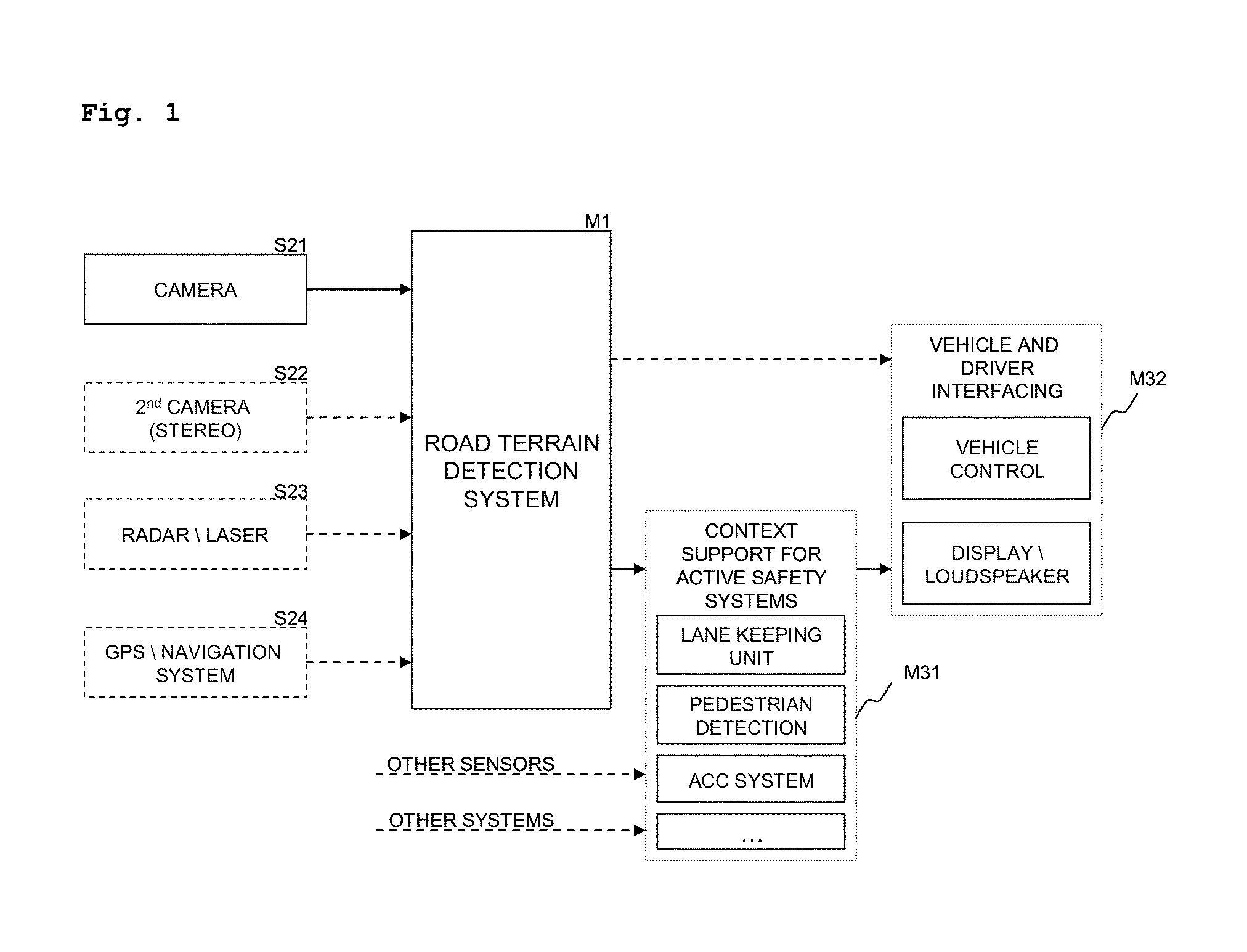
[0085]The method of the present invention that realizes the road terrain detection can be used to provide context information in active safety systems for driver assistance or control information for the generation of motor commands for autonomous driving (see FIG. 1).

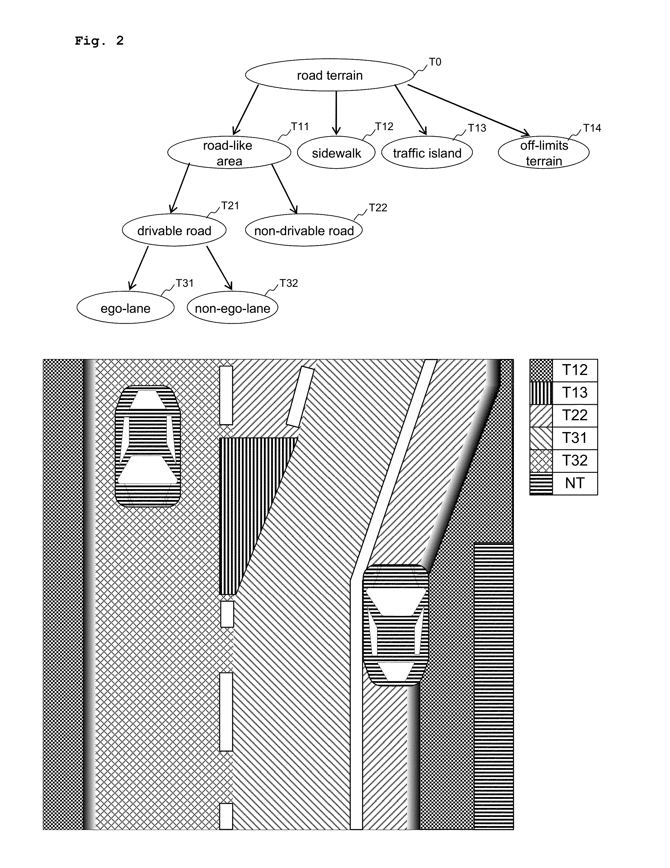
[0086]FIG. 2 shows that road terrain (T0) is categorized into road-like area (T11), sidewalk (T12), traffic island (T13), and off-limits terrain (T14). The road-like area consists of drivable-road (T21) and non-drivable road (T22), wherein drivable road is subdivided in ego-lane (T31, the lane the vehicle drives on) and non-ego-lane (T32, the lane the vehicle does not drive on but other vehicles might drive on). Non-road terrain (NT) describes larger, elevated objects that a vehicle in road scenarios encounters and that cannot be potentially driven over. Such objects are e.g. other cars or vehicles, or buildings. The example image in the lower part of FIG. 2 shows a top view of a road scene illustrating the road terrai...


PUM


Abstract

The present invention describes a road terrain detection system that comprises a method for classifying selected locations in the environment of a vehicle based on sensory input signals such as pixel values of a camera image. The method comprises a high level spatial feature generation for selected locations in the environment called base points. The spatial feature generation of the base points is based on a value-continuous confidence representation that captures visual and physical properties of the environment, generated by so called base classifiers operating on raw sensory data. Consequently, the road terrain detection incorporates both local properties of sensor data and their spatial relationship in a two-step feature extraction process.

Description

[0001]The present invention discloses a road-terrain detection method and a road-terrain detection system for driver assistance systems. Such driver assistance systems may be part of a car, bike, scooter or any other road vehicle.FIELD OF THE INVENTION[0002]The invention is in the field of driver assistance based on computer vision and machine learning. The invention can in particular be implemented in a sensor-based computing module, which can be part of a car, a motorbike, or any other land-based vehicle. The invention can be applied in realistic real-world traffic environments, such as e.g. encountered when driving a car in an unconstrained inner-city scenario.[0003]In modern vehicles a human driver is often assisted by “active safety systems”. Such active safety systems (in the following also referred to as “driver assistance systems”), which can e.g. be a lane keeping assistance system as described in U.S. Pat. No. 6,212,453 B1, physically sense the environment of the vehicle a...

Claims


Application Information

Patent Timeline
Patent Type & Authority Patents(United States)
IPC IPC(8): G06K9/00G01S13/89B62D6/00G01S17/93G01S17/89G01S15/93G01S13/93G01S15/89G06T7/00
CPCG01S13/89B62D6/007G01S13/93G01S15/89G01S15/93G01S17/89G01S17/93G06K9/00798G06T7/0081G06T7/0087G06T2207/20081G06T2207/30256G06T7/11G06T7/143G06V20/588
Inventor FRITSCH, JANNIKKUHNL, TOBIAS
Owner HONDA RES INST EUROPE
Why Eureka
Try Eureka