Illumination apparatus and liquid crystal display apparatus

a liquid crystal display and liquid crystal display technology, applied in lighting and heating apparatus, instruments, organic semiconductor devices, etc., can solve the problems of insufficient enhancement of light utilization efficiency, in particular in semi-transmissive liquid crystal display apparatus, and difficult focal point position of lens face, etc., to enhance reduce the effect of lowering the light utilization efficiency of liquid crystal display apparatus

Inactive Publication Date: 2009-03-19
HITACHI LTD
View PDF6 Cites 18 Cited by
  • Summary
  • Abstract
  • Description
  • Claims
  • Application Information

AI Technical Summary

Benefits of technology

[0024]It is an object of the present invention to make possible suppression of lowering of light utilization efficiency of the liquid crystal display apparatus, caused by optical loss after passing through a lens,

Problems solved by technology

It should be noted that, even when a spherical lens is simply arranged on the organic EL, as described in JP-A-2006-318807, sufficient enhancement of light utilization efficiency cannot be achieved, in particular, in semi-transmissive liquid cryst

Method used


Image

  • Illumination apparatus and liquid crystal display apparatus
  • Illumination apparatus and liquid crystal display apparatus
  • Illumination apparatus and liquid crystal display apparatus

Examples


first embodiment

[0040]Explanation will be given below on a first embodiment of the present invention with reference to FIG. 1 to FIG. 8E.

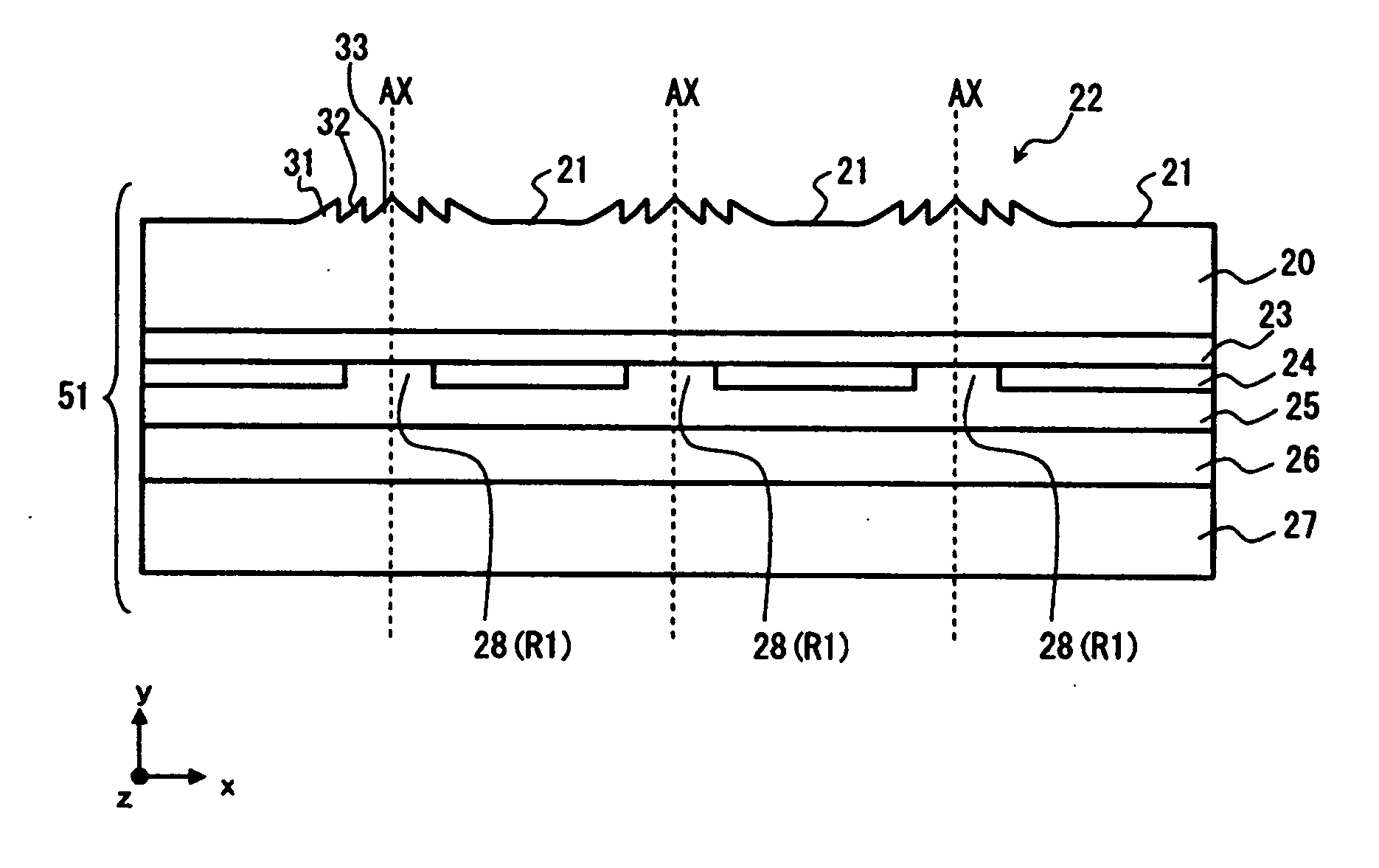
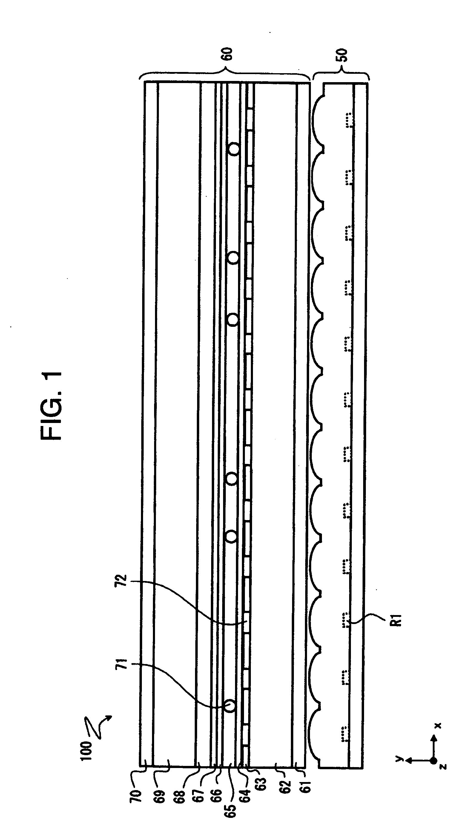
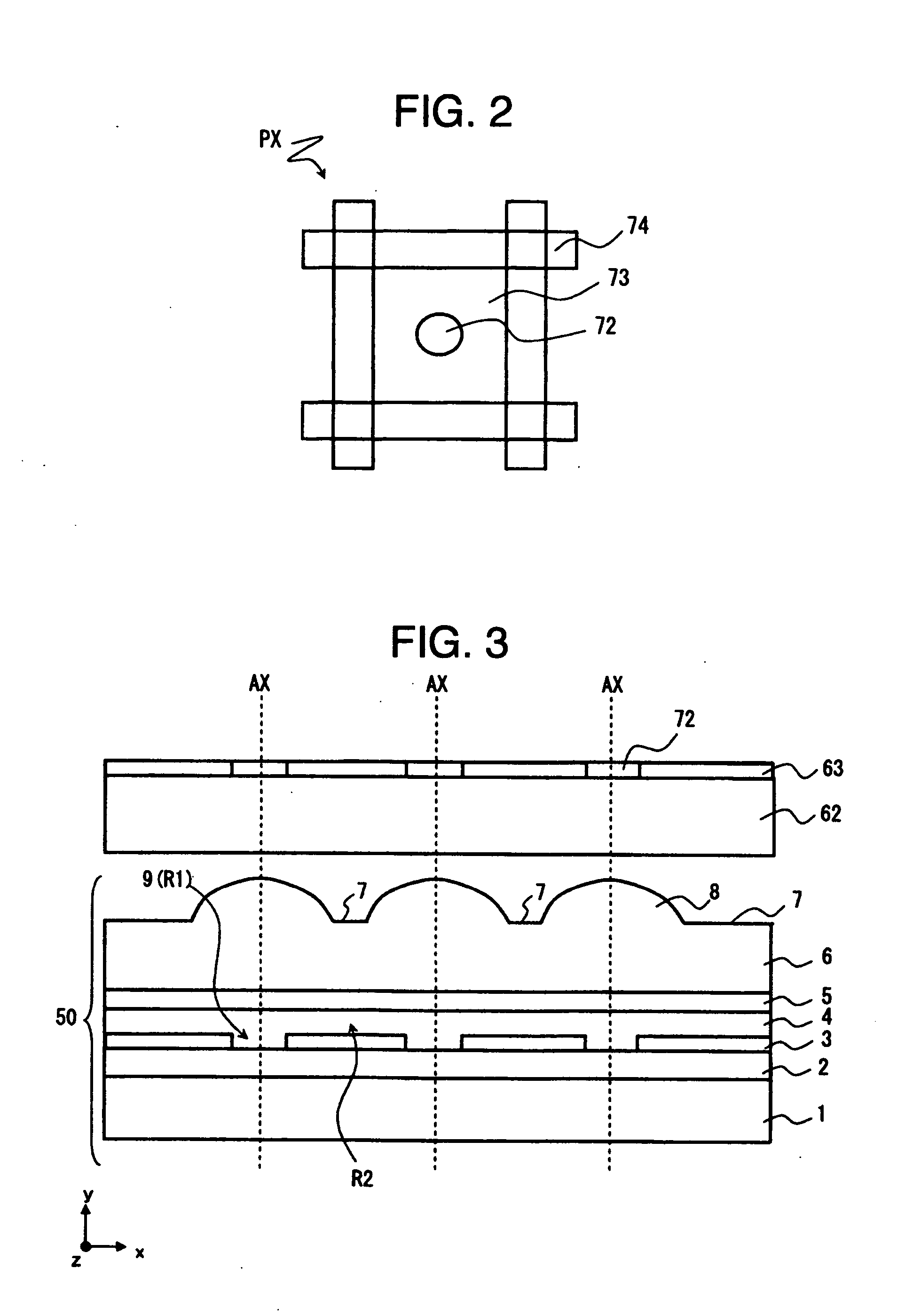
[0041]FIG. 1 is a schematic exemplary diagram for explaining a laminated structure of a semi-transmissive liquid crystal display apparatus. FIG. 2 is a schematic exemplary diagram for explaining a top view configuration of a wiring layer. FIG. 3 is a schematic exemplary diagram for explaining a laminated structure of a back light unit. FIG. 4 is a chart for explaining relation between lens height and directivity. FIG. 5 is a schematic diagram for explaining a lens configuration (a cross-sectional view shape). FIG. 6 is a schematic diagram for explaining a lens configuration (a cross-sectional view shape, a top view shape). FIG. 7 is a schematic diagram for explaining a configuration of a spherical lens (a cross-sectional view shape). FIGS. 8A to 8E are charts for explaining a method for producing a back light unit.

[0042]As shown in FIG. 1, a semi-transmissive liqu...

second embodiment

[0082]Explanation will be given below on a second embodiment of the present invention with reference to FIG. 9 to FIG. 13F.

[0083]FIG. 9 is a schematic exemplary diagram for explaining a laminated structure of a back light unit. FIG. 10 is a schematic diagram for explaining a lens configuration (a cross-sectional view shape). FIG. 11 is a schematic diagram for explaining a lens configuration (a cross-sectional view shape, a top view shape). FIGS. 12A and 12B are schematic exemplary diagrams for explaining variation of a lens configuration (a cross-sectional view shape). FIGS. 13A to 13F are charts for explaining a method for producing a back light unit.

[0084]The back light unit 51 relevant to the present embodiment adopts a lens 22, as shown in FIG. 10. In this way, in addition to the effect explained in the first embodiment, height of the lens itself, which controls directivity of outgoing light, can be set low. In other words, by setting thickness of the lens itself thin, still mor...


PUM


Abstract

Provided is an illumination apparatus for a liquid crystal display apparatus having a plurality of transmission parts arranged two-dimensionally, having a plurality of aspherical lenses, which is installed in response to each of a plurality of the transmission parts and concentrates light for each of a plurality of the transmission parts; a plurality of light emission parts R1 installed in response to each focal point position of a plurality of the aspherical lenses; and an electroluminescence layer containing a non-light emission region R2 installed between a plurality of the light emission parts R1 themselves. Each of a plurality of the aspherical lenses has an inner side lens face containing an intersection with an optical axis AX, and an outer side lens face enclosing said inner side lens face, and curvature in the outer side lens face is smaller than curvature in the inner side lens face.

Description

INCORPORATION BY REFERENCE[0001]The present application claims priority from Japanese application JP-2007-237925 filed on Sep. 13, 2007, the content of which is hereby incorporated by reference into this application.BACKGROUND OF THE INVENTION[0002]The present invention relates to an illumination apparatus and a liquid crystal display apparatus. In particular, the present invention relates to an illumination apparatus suitable to a semi-transmissive liquid crystal display apparatus, and a semi-transmissive liquid crystal display apparatus incorporated with this illumination apparatus.[0003]In recent years, technological progress relating to the liquid crystal display apparatus has been significant. The liquid crystal display apparatus is incorporated also into a mobile phone, a portable personal computer etc., in addition to stationary display. Accordingly, in addition to higher performance of the liquid crystal display apparatus, compact sizing of the liquid crystal display apparat...

Claims


Application Information

Patent Timeline
IPC IPC(8): F21V5/04
CPCG02F1/133603G02F1/133606H01L2251/5361G02F2001/133607H01L51/5275G02F1/133611G02F1/133607H10K50/858G02F1/1335
Inventor SHIBASAKI, TOSHINARISHIMAZAKI, KATSUSUKEARATANI, SUKEKAZUSUGITA, TATSUYA
Owner HITACHI LTD
Why Eureka
Try Eureka