
Self-healing ring-based passive optical network

a passive optical network and self-healing technology, applied in data switching networks, multiplex communication, instruments, etc., can solve problems such as network congestion, delay of rescue work, and production of optical fiber ring faults

Inactive Publication Date: 2009-03-19
IND TECH RES INST
View PDF11 Cites 22 Cited by
  • Summary
  • Abstract
  • Description
  • Claims
  • Application Information

AI Technical Summary

Benefits of technology

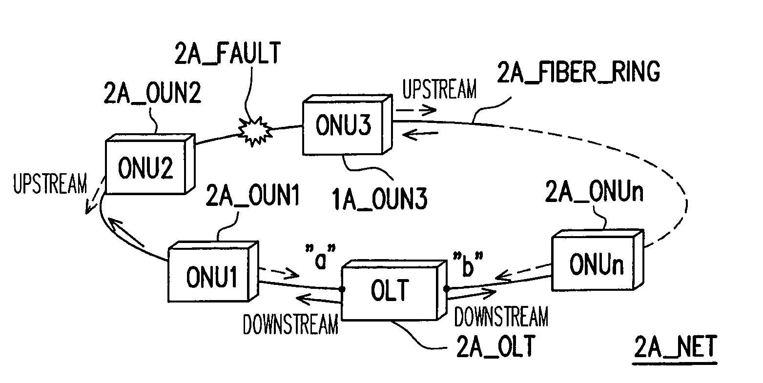
The present invention is about a self-healing ring-based passive optical network (PON). When there is a fault in the optical fiber ring of the PON, the network can still recover and allow optical network units (ONUs) to communicate with each other. The invention provides an adaptable optical line termination (OLT) and ONUs for the self-healing ring-based PON. The OLT includes a transceiver and an optical coupler, which allows for the transmission and reception of signals. The invention allows for the recovery of the PON from faults and ensures continued communication between the OLT and ONUs.

Problems solved by technology

In the conventional communication technique wherein data is transmitted as electric signals, network congestion may be caused due to the bandwidth limitation of the electric signals.
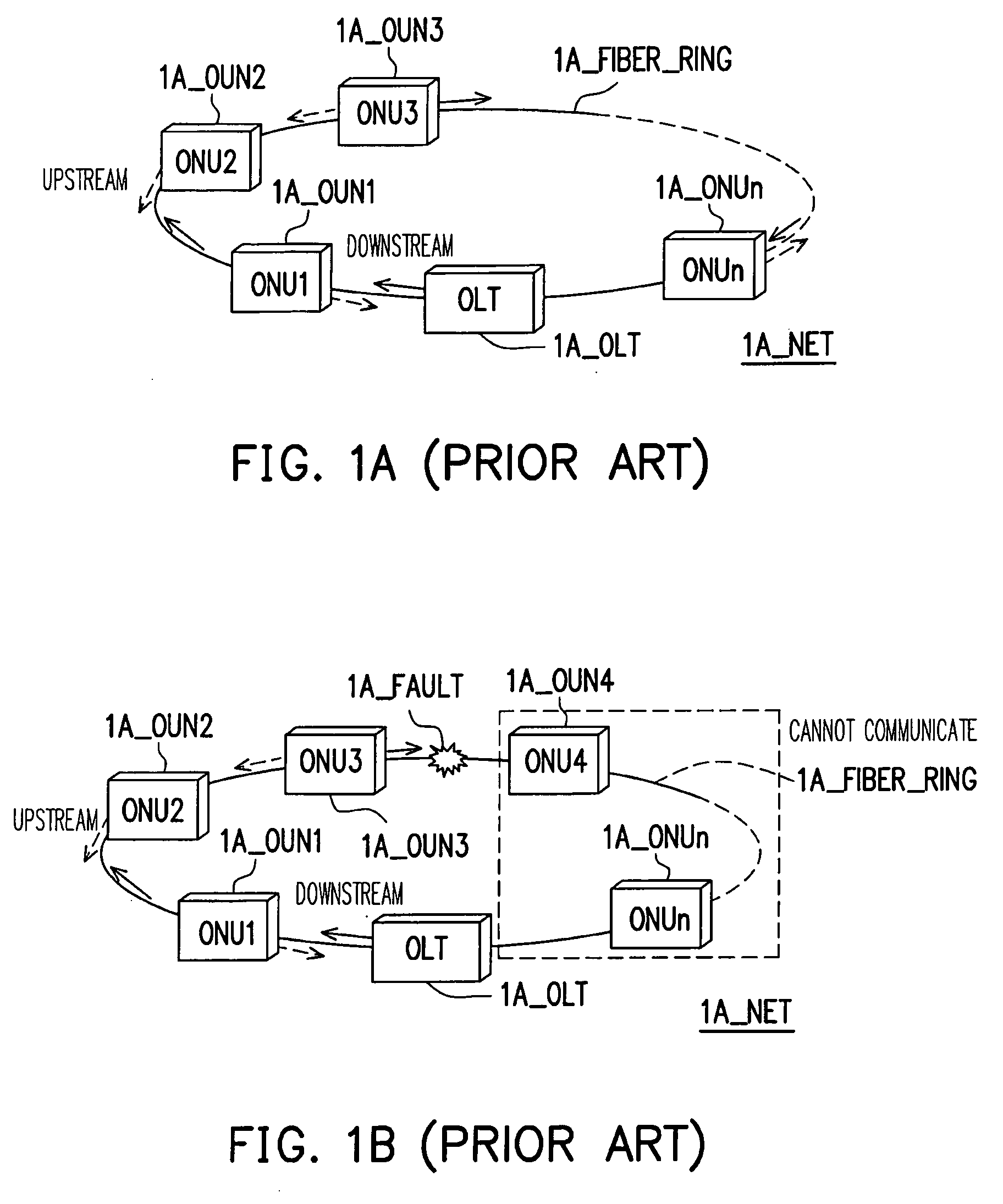
However, a fault may be produced in the optical fiber ring due to some human error (for example, fire) or force majeure (for example, earthquake and typhoon).
If those regions after the fault communicate with other regions through only this ring-based PON and those regions after the fault are in emergency when the fault is produced by some human error or force majeure, rescue work may be delayed due to the communication problem.

Method used


Image

  • Self-healing ring-based passive optical network
  • Self-healing ring-based passive optical network
  • Self-healing ring-based passive optical network

Examples


Embodiment Construction

[0036]Reference will now be made in detail to the present preferred embodiments of the invention, examples of which are illustrated in the accompanying drawings. Wherever possible, the same reference numbers are used in the drawings and the description to refer to the same or like parts.

[0037]In the present invention, an intelligent optical line termination (OLT) and a plurality of optical network units (ONUs) which can both receive and transmit signals are adopted for forming a ring-based passive optical network (PON) which has self-healing function. Thereby, when a fault is produced in an optical fiber ring of the ring-based PON, the OLT automatically detects the fault and the address thereof, and then the OLT switches from unidirectional receiving / transmitting to bidirectional receiving / transmitting so that the ONUs after the fault can still connect to the OLT and communicate with each other.

[0038]According to an exemplary embodiment of the present invention, the OLT further incl...


PUM


Abstract

A self-healing ring-based passive optical network (PON) including an optical fiber ring, an optical line termination (OLT), and a plurality of optical network units (ONUs) is provided. The optical fiber ring has a first end and a second end. The OLT is coupled to the first and the second end. The OLT receives a first signal from the first end or the first and the second end and transmits a second signal to the first end or the first and the second end. Each of the ONUs has a third end and a fourth end both coupled to the optical fiber ring. Each of the ONUs receives the second signal from the third and the fourth end and transmits the first signal to the third and the fourth end. The ONUs connect to the OLT through the optical fiber ring so as to form a ring-based PON.

Description

CROSS-REFERENCE TO RELATED APPLICATION[0001]This application claims the priority benefit of Taiwan application serial no. 96134857, filed on Sep. 19, 2007. The entirety of the above-mentioned patent application is hereby incorporated by reference herein and made a part of this specification.BACKGROUND OF THE INVENTION[0002]1. Field of the Invention[0003]The present invention generally relates to a ring-based passive optical network (PON), in particular, to a self-healing ring-based PON.[0004]2. Description of Related Art[0005]The quantity of data transmitted over networks increases along with the increase in network users. In the conventional communication technique wherein data is transmitted as electric signals, network congestion may be caused due to the bandwidth limitation of the electric signals. Thus, optical fiber communication is adopted by many network service providers for providing various network services to network users.[0006]Optical fiber communication offers greater...

Claims


Application Information

Patent Timeline
Patent Type & Authority Applications(United States)
IPC IPC(8): H04J14/00H04B10/00H04B10/03H04B10/27H04B10/272H04B10/275H04L12/437
CPCH04B10/275H04J14/0226H04J14/0227H04J14/0241H04J14/029H04J14/0291H04J14/0283
Inventor CHI, SIENYEH, CHIEN-HUNG
Owner IND TECH RES INST
Learn More