Process for Drilling a Bore and Corresponding Tool

Inactive Publication Date: 2009-03-19
APEX BRANDS
View PDF47 Cites 24 Cited by
  • Summary
  • Abstract
  • Description
  • Claims
  • Application Information

AI Technical Summary

Benefits of technology

[0017]An object of the invention is therefore to solve those problems by providing a process which permits the drilling

Problems solved by technology

Although such a tool is found to be generally satisfactory, its use for drilling deep bores or materials renowned for being difficult, such as composite materials, may prove to be tricky.
The drilling quality may also be degraded if the drill bit is repositioned incorrectly relative to the bore which has been started.
The pre

Method used


Image

  • Process for Drilling a Bore and Corresponding Tool
  • Process for Drilling a Bore and Corresponding Tool
  • Process for Drilling a Bore and Corresponding Tool

Examples


Embodiment Construction

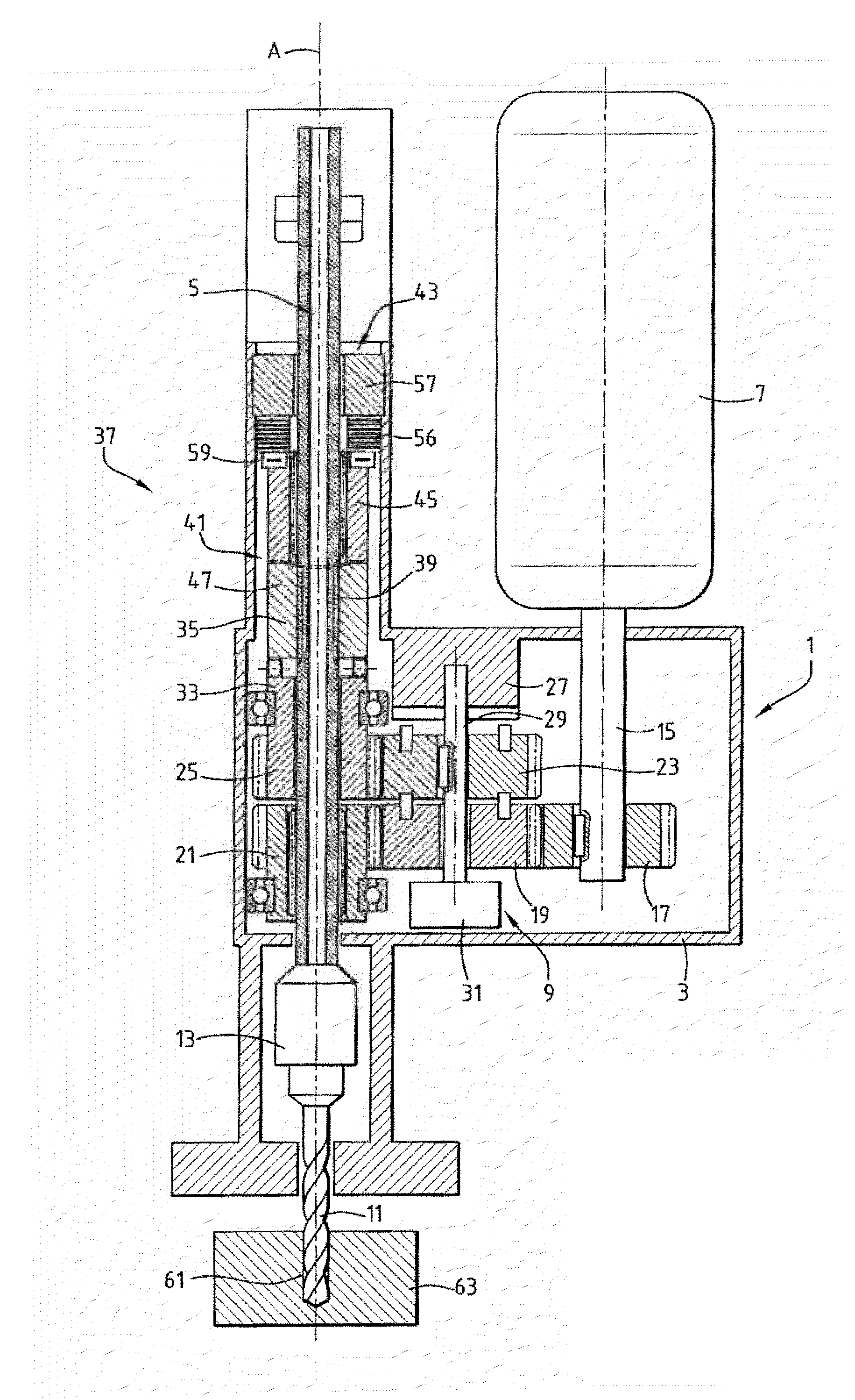
[0036]FIG. 1 illustrates diagrammatically a portable machine tool 1 which comprises principally: a casing 3; a tool-holder spindle 5 extending along a vertical axis A; a motor 7, for example a pneumatic motor; and a mechanism 9 which drives the spindle 5 and which connects the motor 7 and the spindle 5 mechanically. The spindle 5 is received in the casing 3 in such a manner that it is mobile in rotation about its axis A and in translation along that axis A.

[0037]In order to be able to drill bores, a drilling tool 11, in the form of a drill bit, is mounted in a removable manner at the lower end 13 of the spindle 5. The output shaft 15 of the motor 7 carries an output gear wheel 17 which meshes with the drive mechanism 9. In the example shown, the motor 7 is disposed parallel with the spindle 5. However, it could be disposed substantially at right-angles relative to the latter, as explained, for example, in French Patent No. 2,829,952, the contents of which are incorporated herein by ...


PUM

PropertyMeasurementUnit
Heightaaaaaaaaaa

Abstract

In this process for drilling a bore (61), a drilling tool (11) is driven simultaneously in rotation about an axis (A) and in translation along the axis (A) in accordance with an advance movement. The advance movement is combined with an oscillating movement of the drilling tool (11) along the axis (A) of an amplitude sufficient to break up the swarf formed, while at the same time keeping the drilling tool (11) in the bore (61) which is in the process of being drilled. In certain exemplary embodiments, the application may be relevant to the aircraft construction industry.

Description

TECHNICAL FIELD[0001]The present invention relates to a process for drilling a bore, in which process a drilling tool is driven simultaneously in rotation about an axis and in translation along the axis in accordance with an advance movement.[0002]The invention is applicable, for example, to aircraft construction.BACKGROUND TO THE INVENTION[0003]In order to implement such a drilling process in this type of application, use is generally made of a machine tool comprising:[0004]a casing;[0005]a tool-holder spindle extending along an axis;[0006]a mechanism for driving the tool-holder spindle, the mechanism comprising:[0007]a first member for driving the spindle in rotation about its axis relative to the casing;[0008]a second member for driving the spindle in translation along its axis relative to the casing, the second member for driving in translation being screwed onto a threaded portion of the spindle so that the spindle advances or returns along the axis as a function of the relativ...

Claims


Application Information

Patent Timeline
IPC IPC(8): B23B47/18
CPCB23B47/34B23B2260/02B23Q5/326Y10T408/23Y10T408/6771Y10T408/68Y10T408/6793
Inventor JAILLON, JAQUES HENRI
Owner APEX BRANDS
Why Eureka
Try Eureka