Fixation system for bones

a fixation system and bone technology, applied in the field of bone fixation system, can solve the problems of increasing the load, affecting the fixation effect, and unable to achieve uniform effect, so as to achieve the optimal screw position

Inactive Publication Date: 2009-03-19
WOLTER DIETMAR
View PDF12 Cites 80 Cited by
  • Summary
  • Abstract
  • Description
  • Claims
  • Application Information

AI Technical Summary

Benefits of technology

[0023]Since the bone, as a rule, has curved surfaces and this is the case particularly in the area close to joints it is necessary that plate systems, in particular, be adapted to such bone curvatures. As a rule, this operation is accomplished by appropriate bending tools during the surgery. It is also possible here to vary the orientation of plate holes in accordance with the conformation. If a distinct bone surface curvature is found, e.g. in the area close to joints, the screw hole if obliquely placed may make it even easier to achieve an optimal screw position in the bone. This can be taken into account from the very beginning in orienting holes in the plate so that a desired oblique orientation of at least two holes is achieved in the plate upon conformation.
[0024]Preferably, the bone screws may be adapted to be inserted into the holes of the force support under different angles and to be fixed therein. The force support and the screws can be configured here according to the patent applications mentioned at the beginning, particularly according to DE 43 43 117 A1, DE 196 29 011 A1 or P 198 58 889.5, the entire contents of each of which is incorporated by reference in its entirety. The fact that at least two holes are obliquely inclined towards each other in the force support makes it possible to introduce at least two bone screws into the force support so as to be inclined towards each other from the very beginning without using up the clearance furnished by the fixability under different angles. This significantly improves the possibilities to straddle the screws in the bone by giving them an oblique position.

Problems solved by technology

Even if plate systems are used which lack angular stability we will find plate fractures which, as a rule, extend through a plate hole or lead to loosening phenomena with the screws exiting from the bone.
This means that forces which act have no uniform effect on a deformation of the plate or the nail as can be encountered more or less in implants which are not angularly stable, but that these forces cause an intensified load by bending in the area of the screw hole which comes to lie closest to the zone of fracture or instability.
At this stage, a failure of the implant might then occur.

Method used


Image

  • Fixation system for bones
  • Fixation system for bones
  • Fixation system for bones

Examples


Embodiment Construction

[0033]While this invention may be embodied in many different forms, there are described in detail herein a specific preferred embodiment of the invention. This description is an exemplification of the principles of the invention and is not intended to limit the invention to the particular embodiment illustrated.

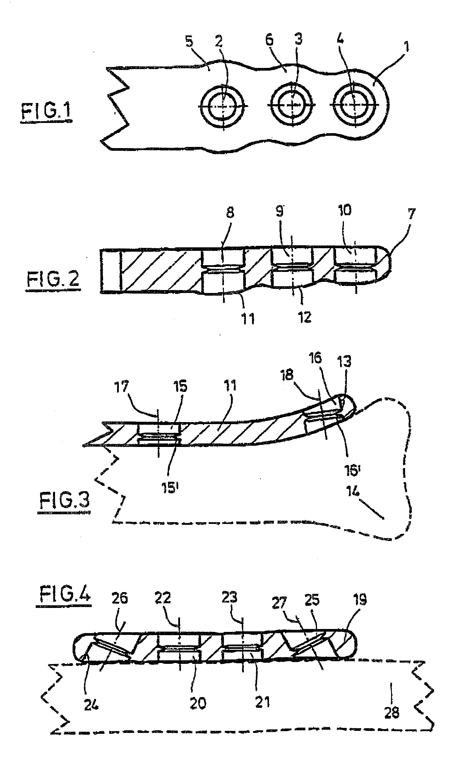
[0034]According to FIG. 1, a bone plate 1 has three plate holes 2, 3, 4 in a portion. Of these, plate hole 2 requires to be disposed nearest to a zone of fracture of instability of a bone, hole 3 requires to be disposed at a larger distance, and hole 4 requires to be disposed at the largest distance therefrom. Bone plate 1 has a reinforcement in the form of a large widened portion 5 around hole 2. There is also a reinforcement in the form of a widened portion 6 at hole 3 which, however, is only half the size of the widened portion 5. There is no longer a widened portion at hole 4, but the bone plate is of a substantial constant width here. The widened portions 5, 5 each consi...


PUM


Abstract

The invention takes the form of a fixation system for bones with a force carrier (1) having holes (2, 3, 4), two of which are adjacent, and bone screws (36 to 41) adapted to be inserted into the holes (2, 3, 4) the heads of the bone screws (36 to 41) and the holes (2, 3, 4) being adapted to fixedly anchor the heads in the holes (2, 3, 4) wherein the two adjacent holes (2) are disposed on different sides of a zone of fracture or instability of a bone, wherein the force carrier (1) has reinforcements (5) at the holes (2) which are at the smallest distance from the zone of fracture or instability of bone and / or the bone screws (36 to 41) adapted to be inserted into said holes (2) have reinforcements, said reinforcements being dimensioned such that they are able to take up 50 to 60 percent of the total load on the fixation system, wherein the force carrier (1) have further reinforcements (6) at the holes (3) adjacent to the holes (2) mentioned first and / or the bone screws (36 to 41) adapted to be inserted into said holes (3) adjacent to the holes (2) mentioned first have further reinforcements, said further reinforcements (6) being dimensioned such that they are able to take up 20 to 30 percent of the total load on the fixation system and the force carrier (1) is provided with holes (4) which are required to be disposed at an even larger distance from the zone of fracture or instability of a bone, the last mentioned holes (4) and / or the bone screws (36 to 41) adapted to be inserted therein being dimensioned such that the last mentioned holes (4) and / or bone screws (36 to 41) are able to take up to rest of the total load on the fixation system.

Description

CROSS-REFERENCE TO RELATED APPLICATIONS[0001]This application is a continuation-in-part of Ser. No. 10 / 070,862, which was a national stage entry of PCT / EP00 / 08999, with an international filing date of Sep. 14, 2000, the entire contents of each of which is hereby incorporated by reference in their entirety.STATEMENT REGARDING FEDERALLY SPONSORED RESEARCH[0002]Not ApplicableBACKGROUND OF THE INVENTION[0003]The invention relates to a fixation system for bones with a force support having holes and bone screws which are insertable into the holes and are fixable there.[0004]If fragments of broken bones have to be joined to each other plate, nail and fixateur systems are available nowadays. Stability in plate and nail systems has been reached hitherto by the fact that if osteosynthetic plates were used bone screws firmly pulled these plates up to the bones in order to achieve a stabilization of the fragments of broken bones by means of the contact pressure which the plate exerts on the bon...

Claims


Application Information

Patent Timeline
Patent Type & Authority Applications(United States)
IPC IPC(8): A61B17/70A61B17/04A61B17/80
CPCA61B17/8057A61B17/80A61B17/8052A61B17/8085
Inventor WOLTER, DIETMAR
Owner WOLTER DIETMAR
Why Eureka
Try Eureka