
Score-based intrusion prevention system

Inactive Publication Date: 2009-03-19
ALCATEL LUCENT SAS
View PDF3 Cites 107 Cited by
  • Summary
  • Abstract
  • Description
  • Claims
  • Application Information

AI Technical Summary

Benefits of technology

[0009]It is believed to be a challenge for security administrators to process a large number of alarms that include many false positives to discover actually concealed attacks. Thus, in various exemplary embodiments, the IPS uses a method that is able to combine the logic of small events to identify a large event from a source or sources or from a target destination or destinations. Accordingly, in various exemplary embodiments, the quantity of false positive alarms generated is significantly reduced. In this manner, various exemplary embodiments achieve a higher accuracy rate for identifying malicious traffic.
[0010]Various exemplary embodiments are external third-party applications called Security Information Management (SIM) systems. However, it is believed that such embodiments substantially increase hardware and software costs and correspondingly increase the complexity of the system. Thus, various exemplary embodiments improve over these disadvantages.

Problems solved by technology

It is believed to be difficult to uniquely identify an attack based on a single anomaly check or a single signature match.
Correspondingly, this lack of dependency often results in many false positive alarms.
It is believed to be a challenge for security administrators to process a large number of alarms that include many false positives to discover actually concealed attacks.

Method used


Image

  • Score-based intrusion prevention system
  • Score-based intrusion prevention system
  • Score-based intrusion prevention system

Examples


second embodiment

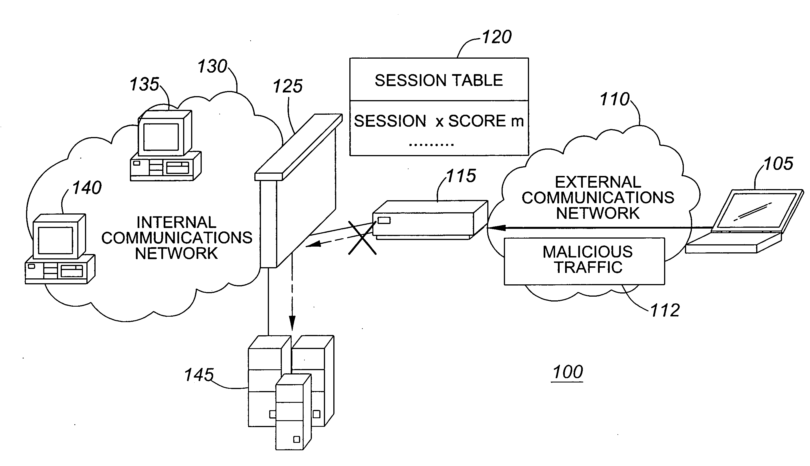
[0030]Thus, exemplary system 100 represents a system where the score-based IPS 115 is deployed outside a perimeter of the internal communications network 130 in front of the firewall 125. A second embodiment similar to exemplary system 100 is shown in FIG. 2.

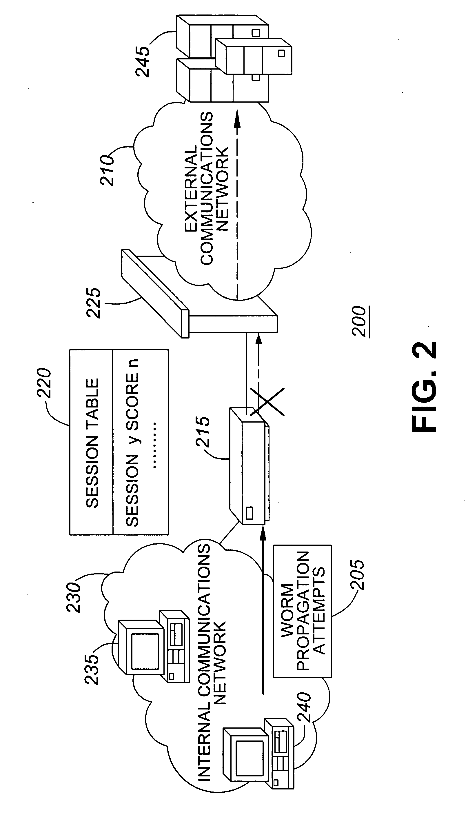
[0031]FIG. 2 is a schematic diagram of a second exemplary embodiment of a score-based intrusion prevention system 200. Exemplary system 200 includes internal communications network 230, score-based IPS 215, firewall 225, external communications network 210 and servers 245.

[0032]In exemplary system 200, worm propagation attempts 205 are initiated within the internal communications network 230 from one of workstation 235 and workstation 240. The worm propagation attempts 205 are received by the score-based IPS 215.

[0033]The score-based IPS 215 creates a session table 220 based on an evaluation of the worm propagation attempts 205. Session table 220 corresponds somewhat to session table 120 as follows. Session indicator Session y i...

third embodiment

[0035]In a third embodiment, not shown, the score-based IPS 115 and / or score-based IPS 215 are included within firewall 125 or firewall 225. The way that score-based IPS 115 and score-based IPS 215 identify undesirable communications and respond to this identification will be described in greater detail below in connection with other figures.

[0036]Generally speaking, exemplary system 100 depicts an exemplary embodiment where a score-based IPS 115 is deployed at the perimeter of a network 130. In contrast, exemplary system 200 depicts an exemplary embodiment where a score-based IPS 215 is deployed behind a firewall 225.

[0037]FIG. 3 is a flow chart of an exemplary method 300 of score-based prevention. The method 300 starts in step 302 and proceeds to step 304.

[0038]In step 304, new packets of data are coming. In other words, new packets of data are being transmitted and received in step 304.

[0039]Following step 304, the method 300 proceeds to step 306. In step 306, protocol decoding o...


PUM


Abstract

A score-based method of preventing intrusion, and related apparatus and systems, including one or more of the following: receiving traffic including new packets; decoding a protocol for same; determining that no session exists to which the packets are associated; creating a session entry for a session corresponding to the packets; setting a total score for the session to zero; performing an anomaly analysis on the packets identifying an anomaly; adding an anomaly score for the anomaly to the total score for the session; determining that the total score for the session does not exceed a threshold; determining that the anomaly analysis is finished; determining that the signature of the received new packets matches a threat signatures; adding a score assigned to the threat signature to the total score for the session; determining that the total score for the session exceeds the threshold; and triggering a threat response action.

Description

BACKGROUND OF THE INVENTION[0001]1. Field of the Invention[0002]This invention relates generally to the prevention of unauthorized computer access.[0003]2. Description of Related Art[0004]The proliferation of attempts to gain unauthorized access to the proprietary computers of others is ubiquitous. Similarly various systems and methods of preventing unauthorized computer access are known. However, there is a need for improved systems and methods of preventing unauthorized computer access.[0005]The foregoing objects and advantages of the invention are illustrative of those that can be achieved by the various exemplary embodiments and are not intended to be exhaustive or limiting of the possible advantages which can be realized. Thus, these and other objects and advantages of the various exemplary embodiments will be apparent from the description herein or can be learned from practicing the various exemplary embodiments, both as embodied herein or as modified in view of any variation ...

Claims


Application Information

Patent Timeline
IPC IPC(8): G06F21/06
CPCH04L63/1416
Inventor SUN, YONGKHAN, FAUD
Owner ALCATEL LUCENT SAS
Learn More