Method of manufacturing flow channel substrate for liquid ejection head

Inactive Publication Date: 2009-03-26
FUJIFILM CORP
View PDF4 Cites 0 Cited by
  • Summary
  • Abstract
  • Description
  • Claims
  • Application Information

AI Technical Summary

Benefits of technology

[0012]The present invention has been contrived in view of these circumstances, an object thereof being to provide a method of manufacturing a flow channel substrate for a liquid ejection head having a flow channel free of a corner section and having good air bubble removal properties, while maintaining desired dimensional accuracy when forming the flow channel.
[0014]In this aspect of the invention, spreading of the dissolvable resin (sacrificial layer) s during heat treatment is prevented, and it is possible to apply a rounded shape to a corner section of the flow channel shape formed by the sacrificial layer, on the side which does not contact with the substrate, while maintaining the dimensional accuracy of the flow channel shape. Consequently, it is possible to obtain a liquid flow channel substrate having a flow channel with improved air bubble removal properties.
[0016]In this aspect of the invention, it is possible to remove the lyophobic film simultaneously with curing the surface of the dissolvable resin layer, simply by radiating vacuum ultraviolet light onto the whole surface of the substrate. This improves the durability of the flow channel shape formed by means of the dissolvable resin layer, as well as improving the processing accuracy during the manufacture of the flow channel.
[0018]In this aspect of the invention, spreading of the dissolvable resin (sacrificial layer) during heat treatment is prevented, and it is possible to apply a rounded shape to a corner section of the flow channel shape formed by the sacrificial layer, on the side which does not contact with the substrate, while maintaining the dimensional accuracy of the flow channel shape. Consequently, it is possible to obtain a liquid flow channel substrate having a flow channel with improved air bubble removal properties.
[0020]In this aspect of the invention, it is possible to prevent spreading of the sacrificial layer during heat treatment, even more reliably, and therefore a rounded shape can be applied to a corner section of the flow channel shape formed by the sacrificial layer, on the side which does not contact with the substrate, while maintaining even better dimensional accuracy of the flow channel shape.
[0021]As described above, according to the present invention, spreading of the dissolvable resin (sacrificial layer) during heat treatment is prevented, and it is possible to apply a rounded shape to a corner section of the flow channel shape formed by the sacrificial layer, on the side which does not contact with the substrate, while maintaining the dimensional accuracy of the flow channel shape. Consequently, it is possible to obtain a liquid flow channel substrate having a flow channel with improved air bubble removal properties.

Problems solved by technology

In this case, if air bubbles which may have entered inside the ink flow channels or which have occurred inside the ink flow channels adhere to positions such as corners of the end portions inside the ink flow channels, then ejection defects may occur since the ink is not supplied correctly.
However, the technology described in Japanese Patent Application Publication No. 9-193405 entails a problem in that when a rounded shape is applied by means of heat treatment to the corner section of the ink flow channel pattern which is formed in a rectangular shape as the dissolvable resin layer, then the dissolvable resin layer (sacrificial layer) 504 becomes broader, as indicated by the reference symbol δ in (b) of FIG. 12, and hence the width of the portion contacting the substrate 500 changes and the dimensional accuracy becomes worse.
Moreover, since narrow corner sections 512 are formed in the corners of the flow channel 510, as shown in (c) of FIG. 12, due to the broadened portions of the sacrificial layer504, then the air bubbles in the liquid (ink) tend to stay in these corner sections, the air bubble removal properties become worse, and this adversely affect the ejection of liquid.

Method used


Image

  • Method of manufacturing flow channel substrate for liquid ejection head
  • Method of manufacturing flow channel substrate for liquid ejection head
  • Method of manufacturing flow channel substrate for liquid ejection head

Examples


first embodiment

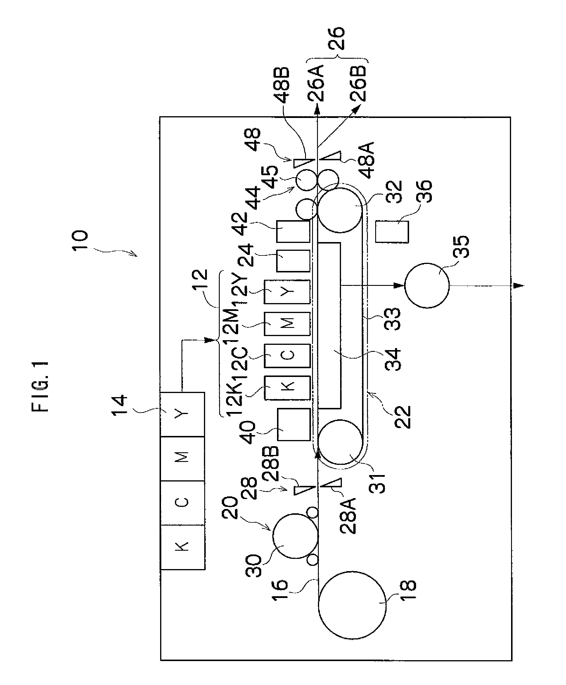
[0035]FIG. 1 is a general schematic drawing showing an inkjet recording apparatus forming an image recording apparatus comprising a liquid ejection head having a flow channel substrate relating to an embodiment of the present invention.

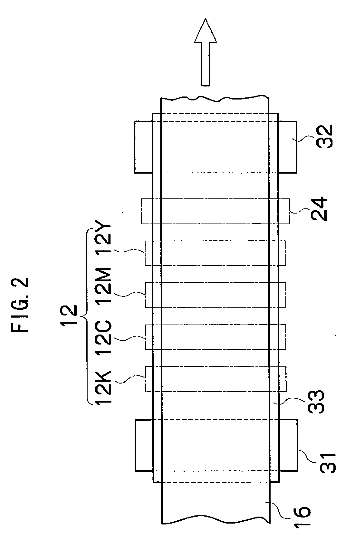
[0036]As shown in FIG. 1, the inkjet recording apparatus 10 comprises: a print unit 12 having a plurality of print heads (liquid ejection heads) 12K, 12C, 12M, and 12Y for ink colors of black (K), cyan (C), magenta (M), and yellow (Y), respectively; an ink storing and loading unit 14 for storing inks of K, C, M and Y to be supplied to the print heads 12K, 12C, 12M, and 12Y; a paper supply unit 18 for supplying recording paper 16; a decurling unit 20 for removing curl in the recording paper 16 supplied from the paper supply unit 18; a suction belt conveyance unit 22 disposed facing the nozzle face (the surface of the nozzle plate formed with nozzles for ejecting ink) of the print unit 12, for conveying the recording paper 16 while keeping the recording...

second embodiment

[0109]Next, a method of manufacturing the flow channel substrate according to the present invention will be described.

[0110]The second embodiment is substantially the same as the first embodiment described above, but it differs in that vacuum ultraviolet light irradiation is used for removing the lyophobic film 114 in transferring from FIGS. 8D and 8E.

[0111]In other words, in the second embodiment, positive resist is used for the sacrificial layer 112 such as a PMER P-LA900PM made by Tokyo Ohka Kogyo Co., Ltd. or an AZ10-XT made by AZ Electronic Materials., fluoroalkyl-silane is used for the lyophobic film 114, and vacuum ultraviolet light is used for removing the lyophobic film 114.

[0112]Apart from the removal of the lyophobic film 114, the second embodiment is the same as the first embodiment, and therefore only the removal of the lyophobic film 114 is described here.

[0113]FIGS. 9A to 9C show steps for removing the lyophobic film 114 according to the second embodiment.

[0114]Firstl...

third embodiment

[0119]Next, the present invention will be described.

[0120]In the third embodiment, an undulating shape (groove / wall) is formed at the perimeter of the sacrificial layer pattern, and this serves to prevent spreading of the sacrificial layer pattern during heat treatment.

[0121]FIGS. 10A to 10G show an example of a case where recess shape grooves are formed, and FIGS. 11A to 11G show an example of a case where projecting shape walls are formed.

[0122]If a recess shape is formed, then firstly, as shown in FIG. 10A, recess shape grooves 124 are formed following the pattern, about the perimeter of the sacrificial layer to be patterned on the substrate 110. There are no particular restrictions on the method of forming the grooves 124, but it is possible, for example, to form the grooves by excavating the substrate by a dry etching or wet etching method, or the like. From the viewpoint of preventing spreading of the sacrificial layer 112 during heat treatment, it is desirable that the corner...


PUM


Abstract

A method of manufacturing a flow channel substrate for a liquid ejection head, includes at least the steps of: forming, on a substrate, a sacrificial layer which is made of a dissolvable resin and has a liquid flow channel shape; forming a lyophobic film on the substrate and the sacrificial layer; applying, by heat treatment, a rounded shape to a corner section of the sacrificial layer on a side which is not in contact with the substrate; removing the lyophobic film after the heat treatment; forming a coating resin layer on the substrate and the sacrificial layer after the lyophobic film is removed; patterning the coating resin layer; and dissolving the sacrificial layer.

Description

BACKGROUND OF THE INVENTION[0001]1. Field of the Invention[0002]The present invention relates to a method of manufacturing a flow channel substrate for a liquid ejection head.[0003]2. Description of the Related Art[0004]Conventionally, as an image forming apparatus, an inkjet recording apparatus (inkjet printer) is known, which comprises an inkjet head (liquid ejection head) having an arrangement of a plurality of nozzles for ejecting ink and which forms images on a recording medium by ejecting ink from the nozzles toward the recording medium, while causing the inkjet head and the recording medium to move relatively to each other.[0005]An inkjet head guides ink from an ink lank to ink chambers pressure chambers) which are connected to nozzles, by means of ink flow channels, and ejects ink from the nozzles by various methods, for instance, by generating a pressure inside the ink chamber.[0006]In this case, if air bubbles which may have entered inside the ink flow channels or which ha...

Claims


Application Information

Patent Timeline
IPC IPC(8): B41J2/14
CPCB41J2/1606B41J2/161B41J2/1628Y10T29/49401B41J2/1631B41J2/1645B41J2/1629B41J2/1639
Inventor YOKOUCHI, TSUTOMU
Owner FUJIFILM CORP
Why Eureka
Try Eureka