Trigger assembly for an archery device

Inactive Publication Date: 2009-03-26
HUNTERS MFG CO INC
View PDF36 Cites 45 Cited by
  • Summary
  • Abstract
  • Description
  • Claims
  • Application Information

AI Technical Summary

Benefits of technology

[0011]According to another aspect, the present invention provides a crossbow for propelling an arrow toward a target comprising a stock to be placed against a shoulder of an archer when firing the crossbow, a flight deck extending along an axis that is generally parallel with a desired flight pattern of the arrow to be propelled from the crossbow. The crossbow further comprises an arm transverse to the flight deck and extending generally away therefrom, and a bowstring coupled adjacent to each distal end of the arm that can be drawn rearward to a drawn position to increase the tension of the bowstring relative to the tension of the bowstring when not in the drawn position. A trigger assembly is provided for selectively releasing the bowstring from the dra

Problems solved by technology

However, the significant force exerted on the string latch by the bowstring while drawn, often reaching hundreds of pounds, is transmitted to the interface between the string latch and the trigger, creating a substantial sliding friction between those components.
This sliding friction between the trigger and the string latch makes moving the trigger relative to the string latch difficult, requiring a significant force to be exerted by the shooter on the trigger to fire the arrow.
Applying a suitable

Method used


Image

  • Trigger assembly for an archery device
  • Trigger assembly for an archery device
  • Trigger assembly for an archery device

Examples


Example

[0018]Certain terminology is used herein for convenience only and is not to be taken as a limitation on the present invention. Relative language used herein is best understood with reference to the drawings, in which like numerals are used to identify like or similar items. Further, in the drawings, certain features may be shown in somewhat schematic form.

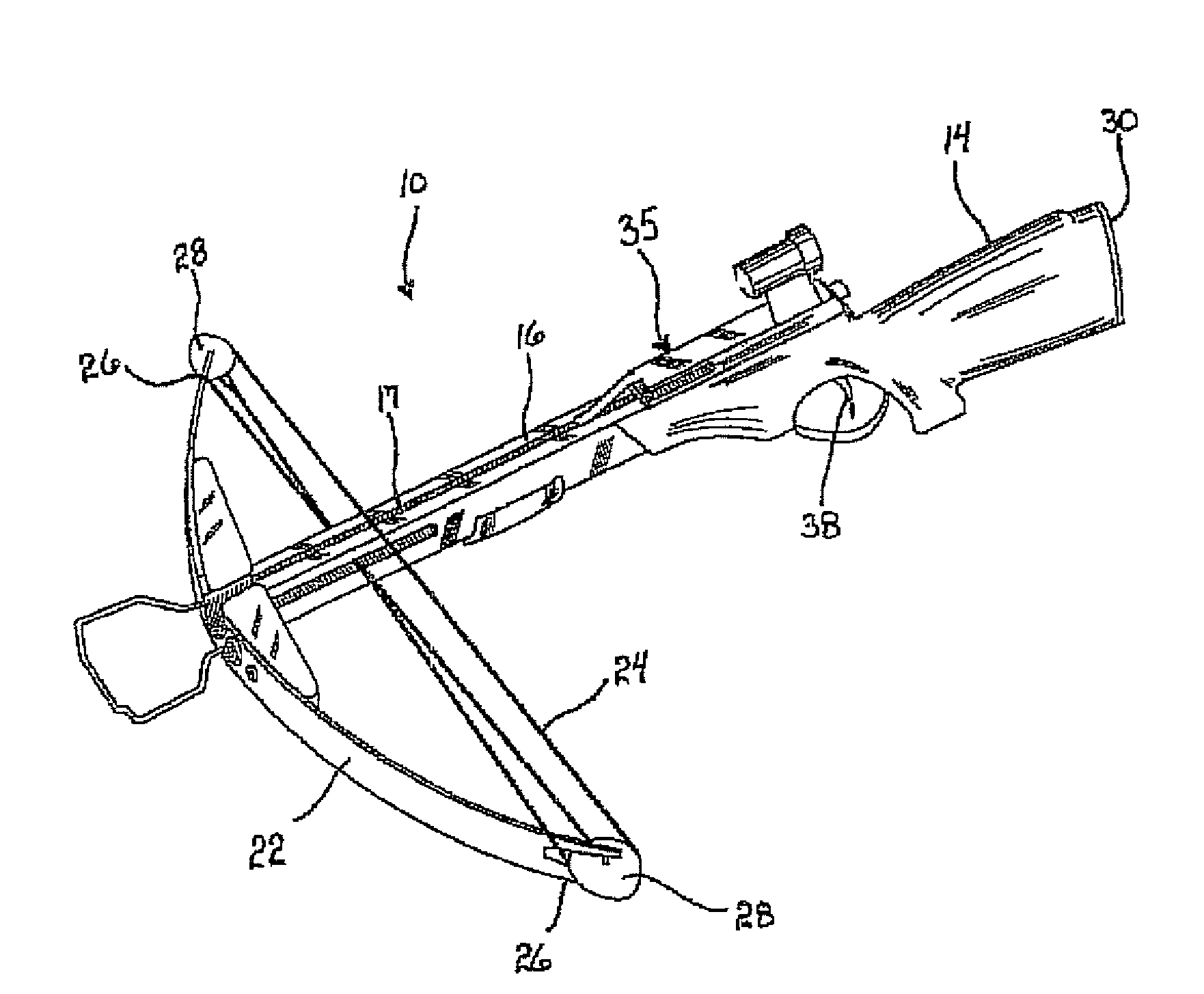
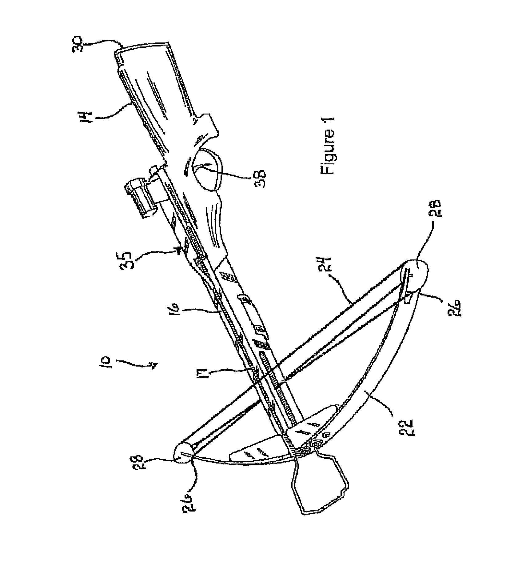
[0019]FIG. 1 illustrates an archery device commonly referred to as a crossbow 10. Crossbows 10 such as that shown in FIG. 1 typically include a stock 14 to be placed against a shoulder of an archer when shooting an arrow from the crossbow 10. A flight deck 16 is coupled to the stock 14 and extends along an axis that is generally parallel with a desired flight pattern of the arrow to be propelled from the crossbow 10. The flight deck 16 is typically fabricated from a metal, a metal alloy, or any rigid material and includes a channel 17 formed therein that receives a member of the arrow's fletching, which is commonly a plastic vane o...


PUM


Abstract

A trigger assembly is disclosed for releasing a bowstring of an archery device from a drawn position to propel an arrow from the archery device toward a target. The trigger assembly includes a guide along which the bowstring is retracted and held in the drawn position; and a pivotal string latch that can be adjusted between a first orientation in which the string latch contacts the bowstring in the drawn position to interfere with the release of the bowstring from the guide, and a second orientation in which the string latch allows the bowstring to be released from the guide. A trigger lever that can be manually actuated by an archer is provided to cause adjustment of the string latch between the first and second orientations, and a roller assembly rolls over a surface of the string latch when the trigger lever is actuated to adjust the orientation of the string latch.

Description

BACKGROUND OF THE INVENTION[0001]1. Field of the Invention[0002]The present invention is directed generally to a trigger assembly, and more specifically, to a trigger assembly for releasing a bowstring from a cocked position via the action of a roller to minimize the force required to be applied to the trigger to cause said release.[0003]2. Description of Related Art[0004]Traditionally, crossbows have normally included a bow having two outwardly extending arms and a bowstring strung between the distal end of each arm for launching an arrow. Similar to a rifle, however, the crossbow also has a stock that can be placed against the shoulder of an archer and a sight that allows the archer to aim the crossbow in a manner similar to aiming the rifle. To load the crossbow, the bowstring is drawn rearwardly toward the stock until it is received within a chamber and locked in place by a latch called the “string latch.” Due to the large forces required of an archer to draw the bowstring rearw...

Claims


Application Information

Patent Timeline
IPC IPC(8): F41A19/10
CPCF41B5/1469F41B5/123
Inventor BEDNAR, RICHARD L.SHAFFER, MICHAEL J.
Owner HUNTERS MFG CO INC
Why Eureka
Try Eureka