
Brake Mechanism for a Caster Wheel on a Offset Rotary Mower

a rotary mower and caster wheel technology, applied in the direction of wheels, agricultural tools and machines, castors, etc., can solve the problems of inability to back up, loss of steering control, and premature wear of tractor tires, and achieve the effect of reducing the side draft load

Inactive Publication Date: 2009-03-26
BATOCHE AG DESIGN
View PDF8 Cites 5 Cited by
  • Summary
  • Abstract
  • Description
  • Claims
  • Application Information

AI Technical Summary

Benefits of technology

[0007]It is the first objective of the invention to provide a braking mechanism that when attached to the front caster wheel or wheels of an offset mower apparatus it would allow the front wheels of rotary mower apparatus to hold some of the draft load thereby reducing the side draft load on the towing vehicle.
[0008]It is a second objective of the present invention that the braking mechanism on the front caster wheel or wheels of the offset mower will allow the offset mower apparatus the ability to back-up when in the offset position on the side slope of the ditch.
[0009]It is a further object of the present invention that the braking mechanism on the front caster wheel or wheels of the offset mower apparatus be operative from the tractor seat allowing the operator ease of applying the brake mechanism as needed.
[0011]When the offset mower apparatus is traveling on the side of a ditch and a steeper area approaches the brake mechanism can be applied through the hydraulic lines or electric cable. This causes the caster wheel(s) at the front to become a fixed wheel(s) allowing the draft load of the mower to shift from an exclusively side draft load on the tractor to a shared load on both tractor and the front wheel assembly of the mower apparatus; thereby reducing the side draft load on the tractor and improving steering control while decreasing rear tire wear on the tractor.

Problems solved by technology

This side draft load can result in premature wear on the tractor tires as well as loss of steering control if the side draft load exceeds the weight of the tractor.
A second problem that occurs with the offset mower is its inability to be backed-up when on the side slope of the ditch.
This inability to back-up can result in costly downtime when the mower inadvertently runs into an obstacle like a culvert and becomes hung up.

Method used


Image

  • Brake Mechanism for a Caster Wheel on a Offset Rotary Mower
  • Brake Mechanism for a Caster Wheel on a Offset Rotary Mower
  • Brake Mechanism for a Caster Wheel on a Offset Rotary Mower

Examples


Embodiment Construction

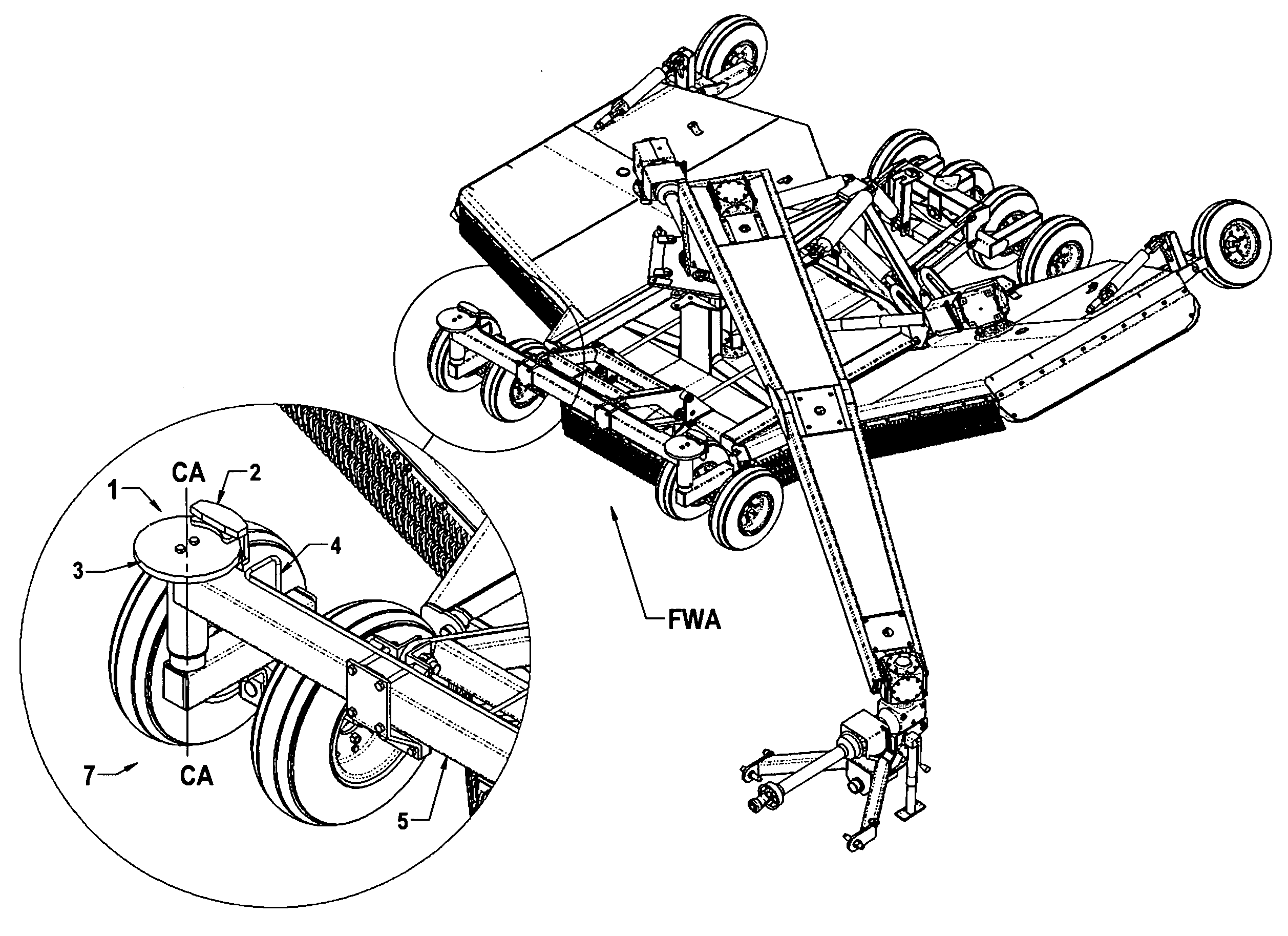
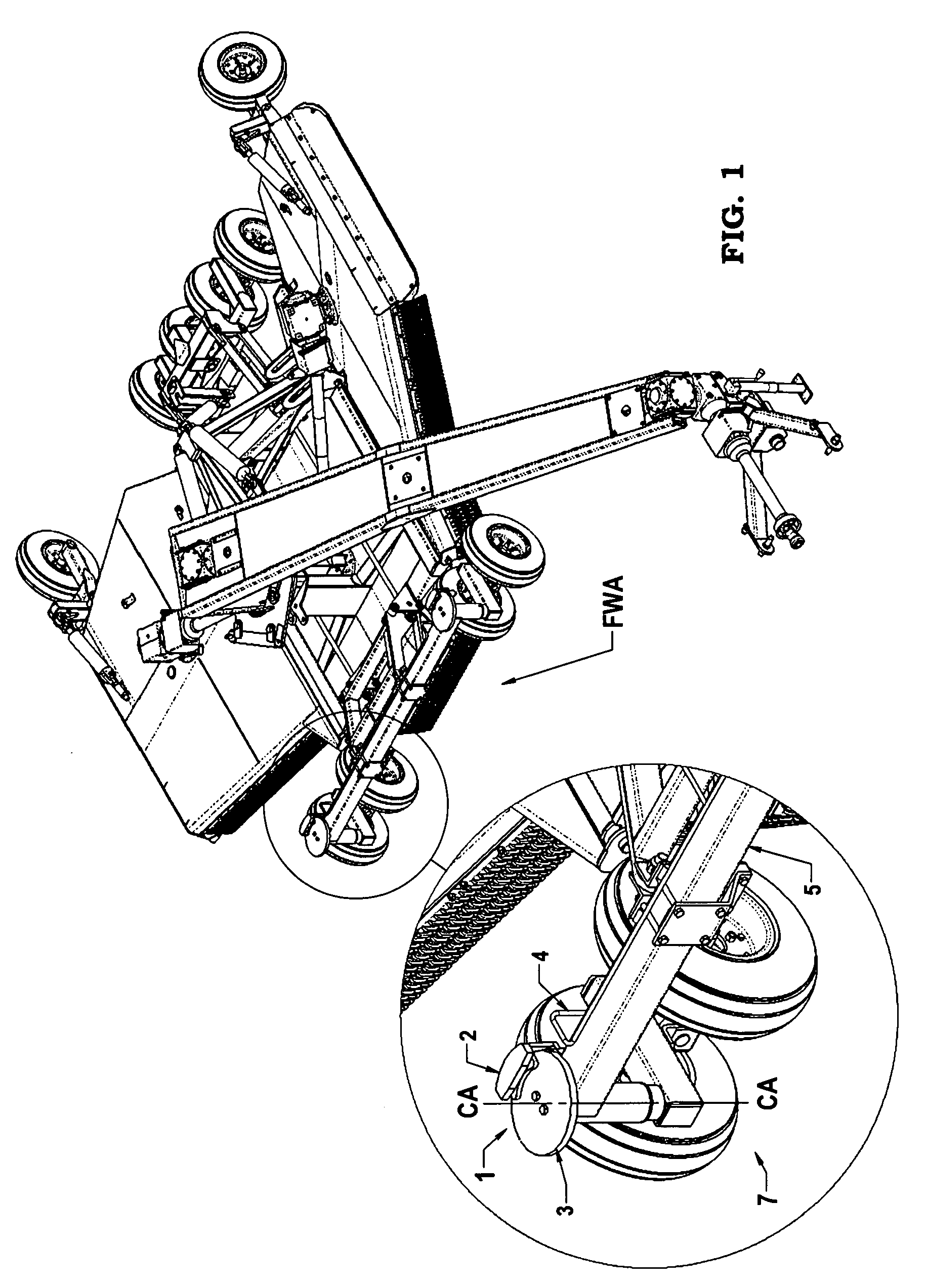
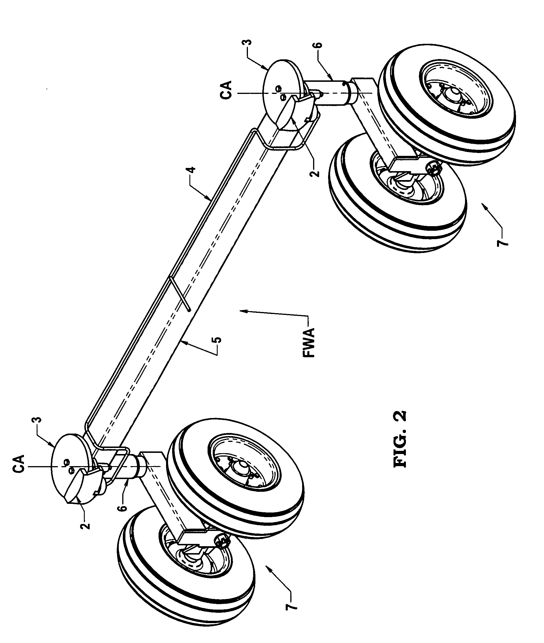
[0016]FIG. 1 illustrates the brake mechanism of the invention for attachment to a caster wheel of an offset rotary mower apparatus to enable a back-up maneuver on a side slope of a ditch and to assist the tractor on steep slopes. This is done by remotely applying the brake mechanism 1. This results in the front caster wheels 7 temporarily becoming a fixed wheel system enabling the offset rotary mower apparatus to be backed-up on the slope of the ditch, because the wheels will follow straight instead of falling down the slope and jack knifing. When the brake mechanism 1 is applied on steep slopes as needed, the fixed wheels will allow the front wheel assembly FWA to take on some of the draft load of the mower. Thus improving steering control on the tractor and reducing rear tire wear. The brake mechanism 1 comprises a brake caliper 2, a brake rotor 3 and hydraulic lines 4 or an electric cable for actuating the brake caliper 2 remotely from the tractor.

[0017]FIG. 2 illustrates the bra...


PUM


Abstract

A brake mechanism for a caster wheel(s) on an offset rotary mower apparatus wherein a hydraulic line or electric cable is connected at one end to the brake mechanism and at the other end to the tractor for remote control operation of the brake mechanism. The brake mechanism which is attached about the vertical caster axis of the caster wheel allows the caster wheel(s) to temporarily become a fixed wheel(s) when needed, assisting in reducing side draft load on the towing vehicle when the offset rotary mower apparatus is on steep slopes and enabling the offset rotary mower apparatus to be backed-up on the side slope of a ditch.

Description

[0001]This invention is in the field of rotary mowers and in particular a brake mechanism for a caster wheel on an offset rotary mower. The brake mechanism allows the caster wheel to temporarily become a fixed wheel assisting in reducing side draft on the towing vehicle when the rotary mower is on a steep slope. The brake mechanism further assists by enabling the rotary mower to be backed-up on the side slope of the ditch.BACKGROUND OF THE INVENTION[0002]Offset rotary mowers are used to maintain roadside ditches. Such offset apparatus' for ditch maintenance are disclosed in U.S. Pat. No. 6,854,250 to Boyko and U.S. Pat. No. 6,739,612 to Calistro. These offset rotary mowers require front wheels to support the front end of the mower when in the offset position. These wheels or wheel is usually a caster wheel to allow free movement of the mower from a tow behind position to an offset position in the ditch. When the mower is in the offset position from the tractor there is a side draft ...

Claims


Application Information

Patent Timeline
IPC IPC(8): A01D69/10
CPCA01D69/10B60B33/0021B60B33/0042B60B33/0049B60B33/026B60B33/0068B60B33/0073B60B33/023B60B33/0057
Inventor BOYKO, STANLEY JOSEPH
Owner BATOCHE AG DESIGN
Learn More