Hybrid Magnetic Bearing

a magnetic bearing and hybrid technology, applied in the direction of magnetic bearings, mechanical devices, windings, etc., can solve the problems of limiting the amount of control force that can be increased, unable to generate strong control force, and large power consumption, so as to achieve high efficiency, reduce size, and increase rigidity

Active Publication Date: 2009-03-26
IWAKI
View PDF8 Cites 33 Cited by
  • Summary
  • Abstract
  • Description
  • Claims
  • Application Information

AI Technical Summary

Benefits of technology

[0027]According to the present invention, higher stiffness, higher efficiency, and further reduction in size can be realized by controlling the bias flux density by the control flux.

Problems solved by technology

A magnetic bearing utilizes an electromagnet and requires a large amount of electrical current to levitate a rotor, resulting in a large power consumption.
However, the magnetic bearings disclosed in Patent Documents 1 and 3 are of configurations in which a permanent magnet is arranged on a magnetic path where the flux of a control coil travels, and because the permanent magnet is a gap for the control flux, there is a limit to the amount that the control force can be increased by increasing the bias flux and increasing the thickness of the permanent magnet.
Although the magnetic bearing disclosed in Patent Document 2 can generate a strong control force if the control is in the X axis direction only or in the Y axis direction only, the simultaneous control of the X axis and Y axis causes a problem such that the strong control force cannot be generated because the control flux is being interfered with.
Because the magnetic bearing suspends a rotor without contact, the magnetic levitation is normally unstable and therefore needs to be stabilized by detection of the position of levitation and by feedback control.
As a sensor detecting the position of levitation, an eddy-current sensor and an inductor sensor are used; however, these are generally expensive.
In addition, if the magnetic bearing and the sensor have to be separately placed, the stability range of the feedback system will be small and there might be difficulty in stabilization.
In particular, magnetic bearings for ultra-small rotors have been sought in recent years, and limitations in the sensor placement space are a problem in reducing the size.
However, the magnetic bearing employing the self-sensing has a problem in that estimation accuracy of the position is lower than that of a method that employs a displacement sensor separately.

Method used


Image

  • Hybrid Magnetic Bearing
  • Hybrid Magnetic Bearing
  • Hybrid Magnetic Bearing

Examples


embodiment 1

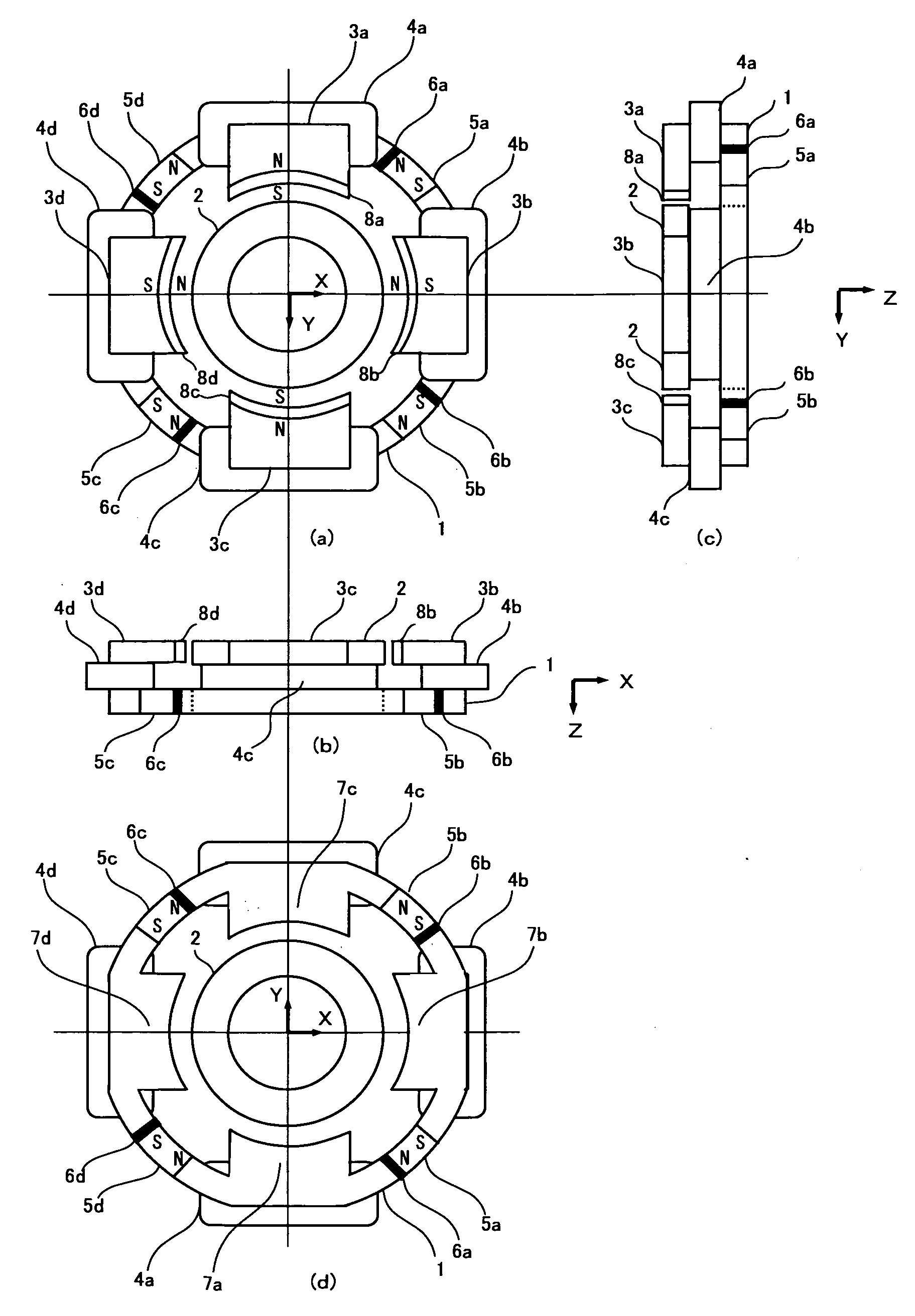
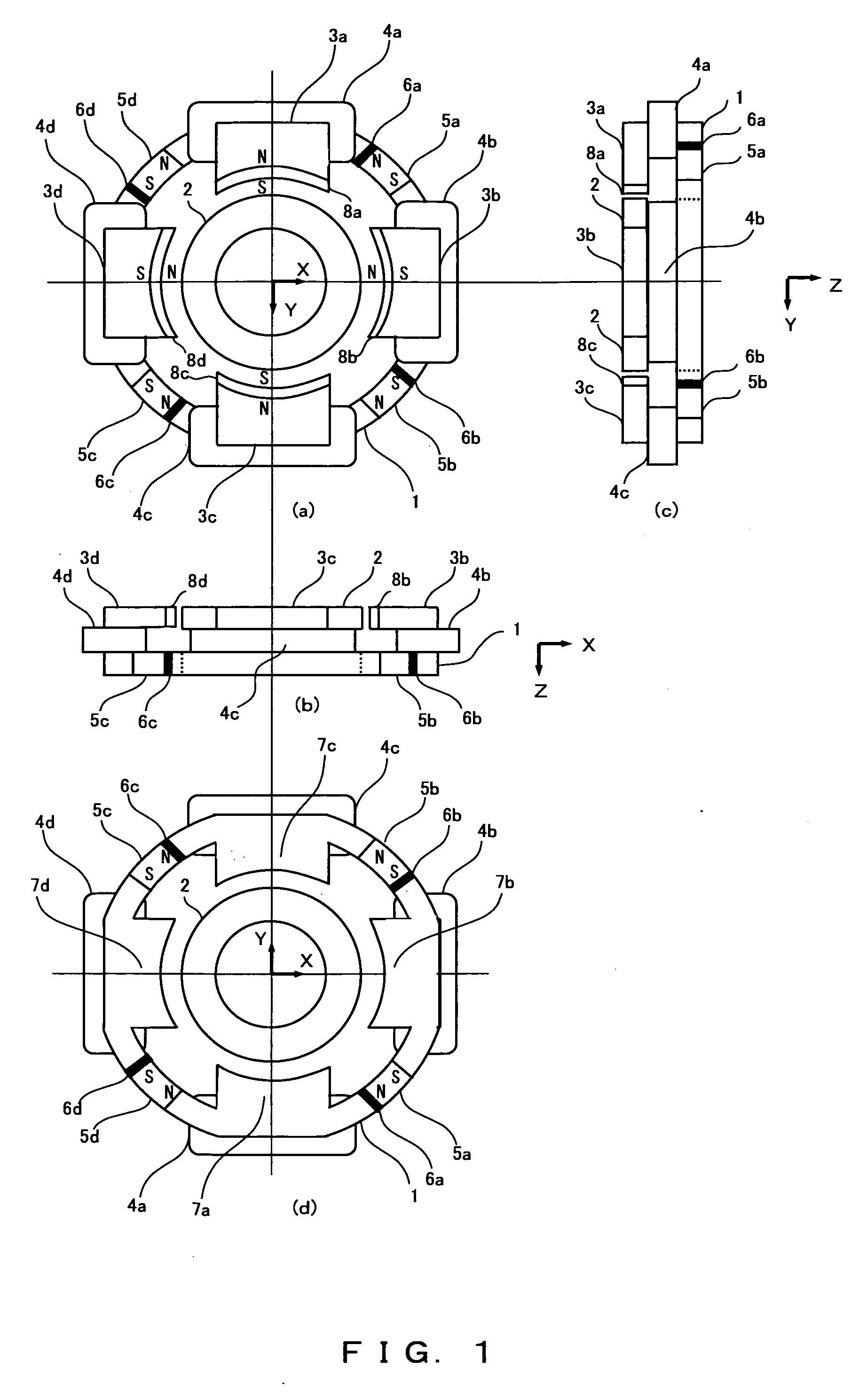
[0042]FIG. 1 shows a development view of the hybrid magnetic bearing of the present invention. FIG. 1(a) is a diagram viewed from commutating poles 3a-3d. FIG. 1(b) is a side view viewed from commutating pole 3c. FIG. 1(c) is a side view viewed from commutating pole 3b. FIG. 1(d) is a diagram viewed from main poles 7a-7d.

[0043]The hybrid magnetic bearing shown in FIG. 1(a)-(d) consists of a stator 1 and a rotor 2. The stator 1 has a first commutating pole 3a, a second commutating pole 3b, a third commutating pole 3c, and a fourth commutating pole 3d which are provided in a protruding condition to the rotor 2; a first control coil 4a, a second control coil 4b, a third control coil 4c, and a fourth control coil 4d; a first permanent magnet 5a, a second permanent magnet 5b, a third permanent magnet 5c, and a fourth permanent magnet 5d; a first sensor 6a, a second sensor 6b, a third sensor 6c, and a fourth sensor 6d; a first main pole 7a, a second main pole 7b, a third main pole 7c, an...

embodiment 2

[0065]FIG. 8 explains a case of a control in which main poles 71b, 71d, 71f, and 71h, and commutating poles 71a, 71c, 71e, and 71g are arranged on the same plane, and control fluxes are generated in control coils 72a-72d. FIG. 8 explains only a case of the control in the X direction for convenience. A bias flux b75a shown in FIG. 7 forms a magnetic path traveling from the positive pole of a commutating pole permanent magnet 74d at the end of the commutating pole 71a to the main pole 71b via a rotor 75. A bias flux b75b forms a magnetic path traveling from the positive pole of a commutating pole permanent magnet 74a at the end of the commutating pole 71c to the core, to the main pole 71d and to the rotor 75. The bias flux b75c forms a magnetic path traveling from the positive pole of a commutating pole permanent magnet 74b at the end of the commutating pole 71e to the main pole 71f via a rotor 75. A bias flux b75d forms a magnetic path traveling from the positive pole of a commutatin...

embodiment 3

[0073]FIG. 9 is a development view of the configuration of Embodiment 3. FIG. 9(a) is a top view. FIG. 9(b) is a side view viewed from the control coils 82c and 82g end. FIG. 9(c) is a side view viewed from the commutating poles 82d and 82f end. FIG. 9(d) is a bottom view.

[0074]The hybrid magnetic bearing of the present invention shown in FIGS. 9(a)-9(d) has a configuration having a magnetic bearing that controls a rotor 81 upward and downward of the rotor 81.

[0075]The upper magnetic bearing has control coils 82a-82d, first through fourth cores 83a-83d, and first through fourth permanent magnets 84a-84d. The first through fourth cores 83a-83d have the first through fourth main poles 85a-85d and the first through fourth commutating poles 87a-87d projecting toward the rotor 81, and each of the main poles 85a-85d opposite to each of the commutating poles 87a-87d, respectively. Here, it is desirable that the first through fourth main poles 85a-85d and the first through fourth commutatin...


PUM


Abstract

In a hybrid magnetic bearing, the electromagnet has a core wound with a control coil and has a main pole and a commutating pole with a commutating pole permanent magnet provided approximately parallel to each other at predetermined intervals in a protruding condition radially or axially to the rotor. In the magnetic bearing provided radially, two electromagnets are placed oppositely to each other across the rotor in an approximately horizontal position, and the rotor is arranged so as to have a predetermined gap with the main pole and the commutating pole, and the permanent magnet is provided between the adjacent electromagnets. In the magnetic bearing provided axially, two electromagnets are placed in parallel in an approximately horizontal position, and the rotor is arranged so as to have a predetermined gap with the main pole and the commutating pole, and the permanent magnet is provided between the adjacent electromagnets.

Description

TECHNICAL FIELD[0001]The present invention relates to a hybrid magnetic bearing that suspends a rotor by magnetic force without contact, and particularly to a technology that allows an electromagnet to reduce power consumption and to improve responses to a control by employing the bias flux of a permanent magnet.BACKGROUND ART[0002]With the technological development in recent years of a magnetic bearing that suspends a rotor without contact, magnetic bearings are being used for various types of bearings. A magnetic bearing utilizes an electromagnet and requires a large amount of electrical current to levitate a rotor, resulting in a large power consumption. Therefore, in order to obtain a large amount of magnetic force with a small amount of current, the space between the rotor and stator is required to be narrow. Additionally, a high work accuracy is required. For those reasons, a hybrid magnetic bearing utilizing the bias flux of a permanent magnet is used.[0003]One basic configur...

Claims


Application Information

Patent Timeline
Patent Type & Authority Applications(United States)
IPC IPC(8): F16C32/04
CPCF16C32/048F16C32/0465F16C32/00F16C32/04
Inventor ONUMA, HIROYUKIMASUZAWA, TORUOKADA, YOHJI
Owner IWAKI
Why Eureka
Try Eureka