Display Device

Inactive Publication Date: 2009-03-26
PANASONIC LIQUID CRYSTAL DISPLAY CO LTD +1
View PDF24 Cites 39 Cited by
  • Summary
  • Abstract
  • Description
  • Claims
  • Application Information

AI Technical Summary

Benefits of technology

[0028]According to the present invention, the air hole is formed in the lower transparent-electrode-attached film of the touch panel which is adhered to the display panel and hence, in adhering the touch panel to the display panel in a vacuum atmosphere, there is no possibility that air in the touch panel expands so as to curve the lower transparent-electrode-attached film. Accordingly, it is possible to eliminate possibility that air is entangled in the UV curing resin when curing such resin so that bubbles are generated in the UV curing resin. Accordingly, the touch panel and the display panel can be directly adhered to each other thus preventing the reflection of light on the interface and, at the same time, decreasing a thickness of the liquid crystal display device per se.
[0029]Further, since the expansion of air in the touch panel can be eliminated, it is possible to prevent the occurrence of a phenomenon that the upper transparent-electrode-attached film swells in a projecting manner so that the upper transparent-electrode-attached film is plastically deformed whereby the formation of a gap between the upper transparent-electrode-attached film and the lower transparent-electrode-attached film becomes unstable.

Problems solved by technology

That is, when the reflection of light exists on the respective interface, it is difficult for a viewer to observe an image.
The direct adhesion of a touch panel and a liquid crystal display panel to each other using an adhesive agent gives rise to various problems.
Such a liquid crystal display device is treated as a defective product.
That is, the lower transparent-electrode-attached film is liable to catch the air at the time of adhesion.

Method used


Image

  • Display Device
  • Display Device
  • Display Device

Examples


embodiment 1

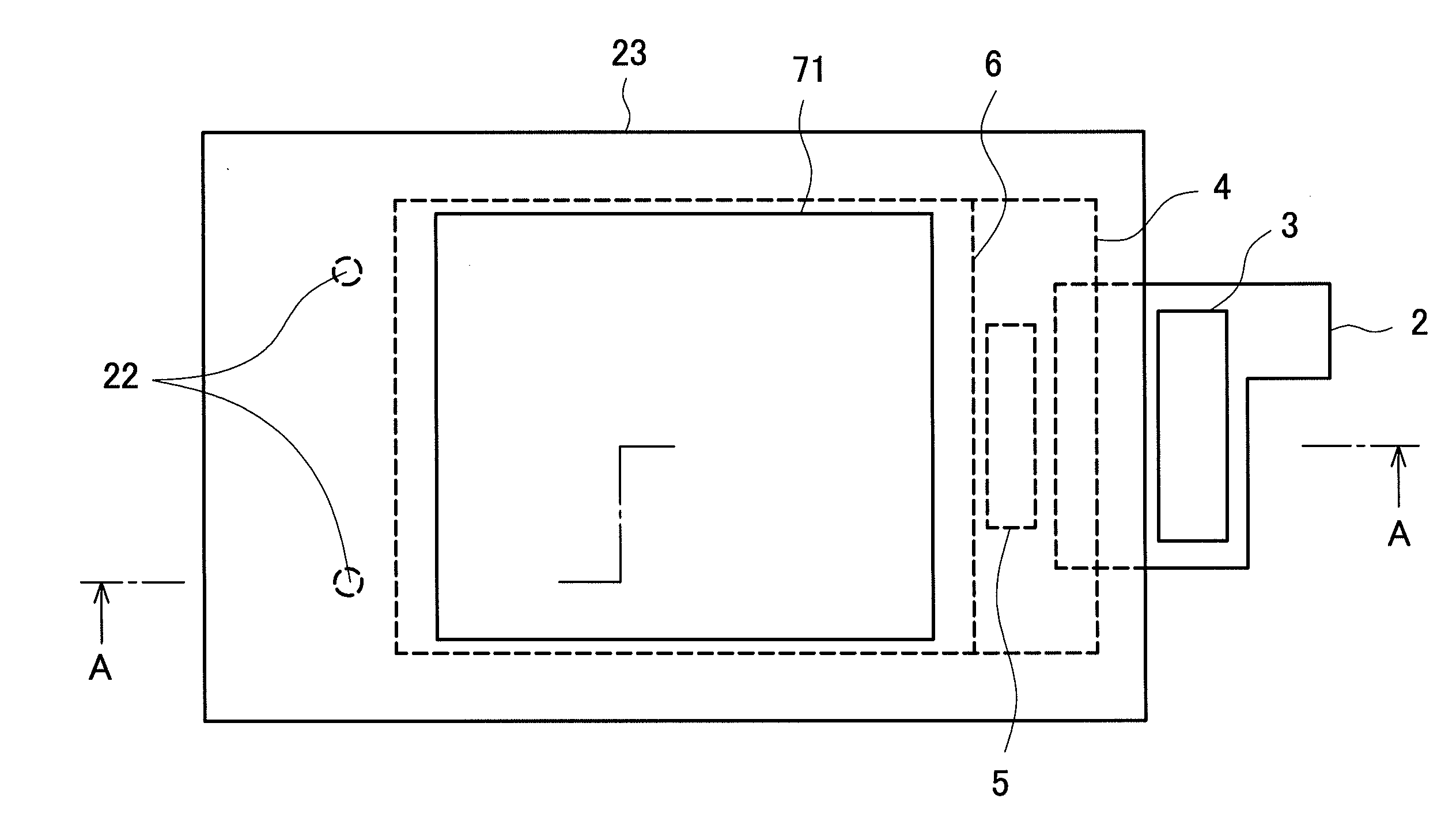
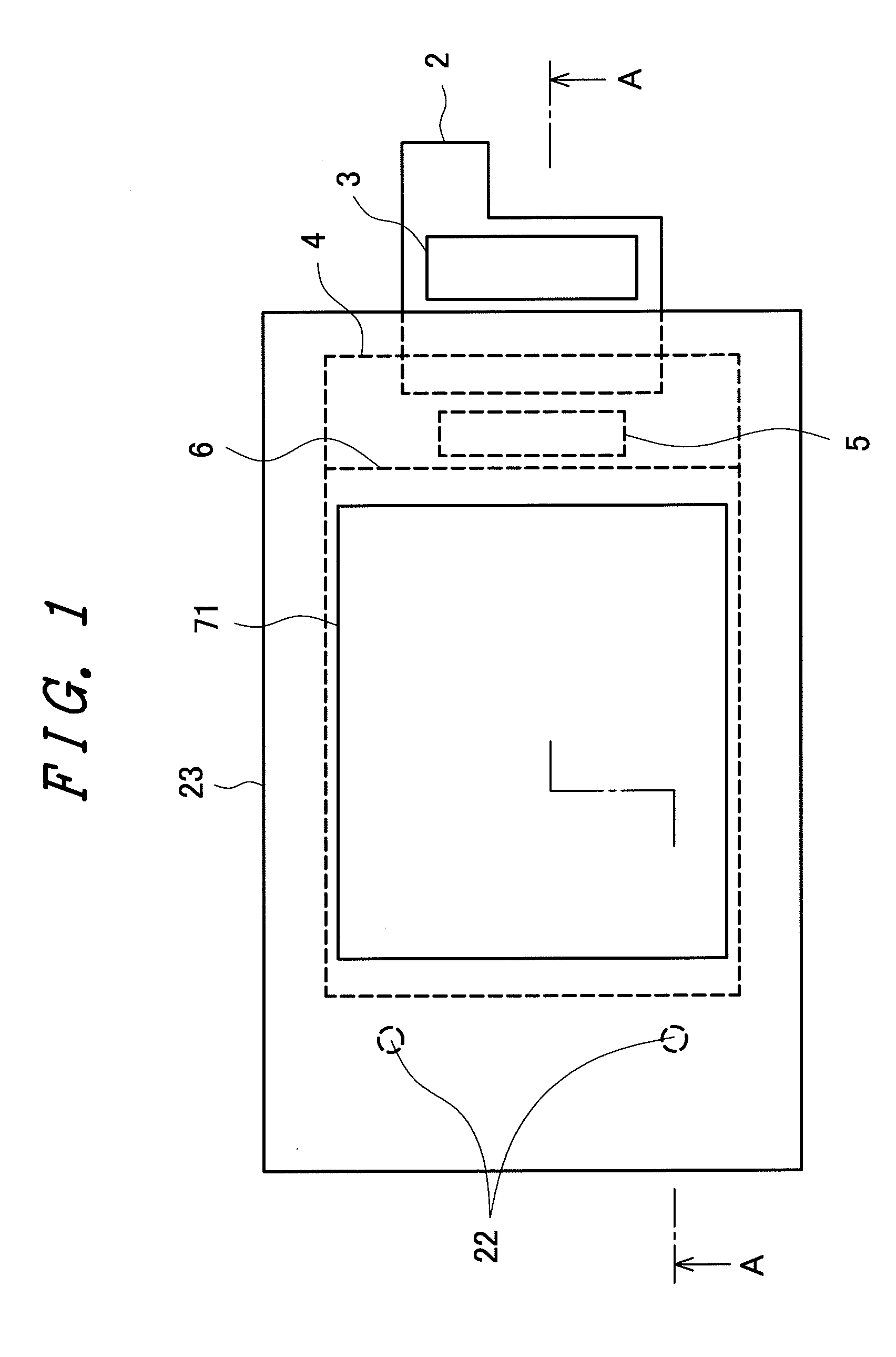
[0044]FIG. 1 is a plan view of a liquid crystal display device having a touch panel according to the present invention. In FIG. 1, a touch panel 23 is formed on a front surface of the liquid crystal display device in a visible manner. The touch panel 23 is covered with a light blocking layer 14 except for a display region 71. Air holes 22 are formed in a lower transparent-electrode-attached film 11 arranged on a back side of the touch panel 23 so as to allow the inside and the outside of the touch panel 23 to communicate with each other. The touch panel 23 is adhered to a color-filter-substrate-6 side of a liquid crystal display panel 24.

[0045]In FIG. 1, for mounting a driving IC 5, a flexible printed circuit board 2 and the like on a TFT-substrate-4 side of the liquid crystal display panel 24, the TFT substrate 4 is made larger than a color filter substrate 6. Although a flexible printed circuit board 2 is provided for connecting the liquid crystal display panel 24 and an external ...

embodiment 2

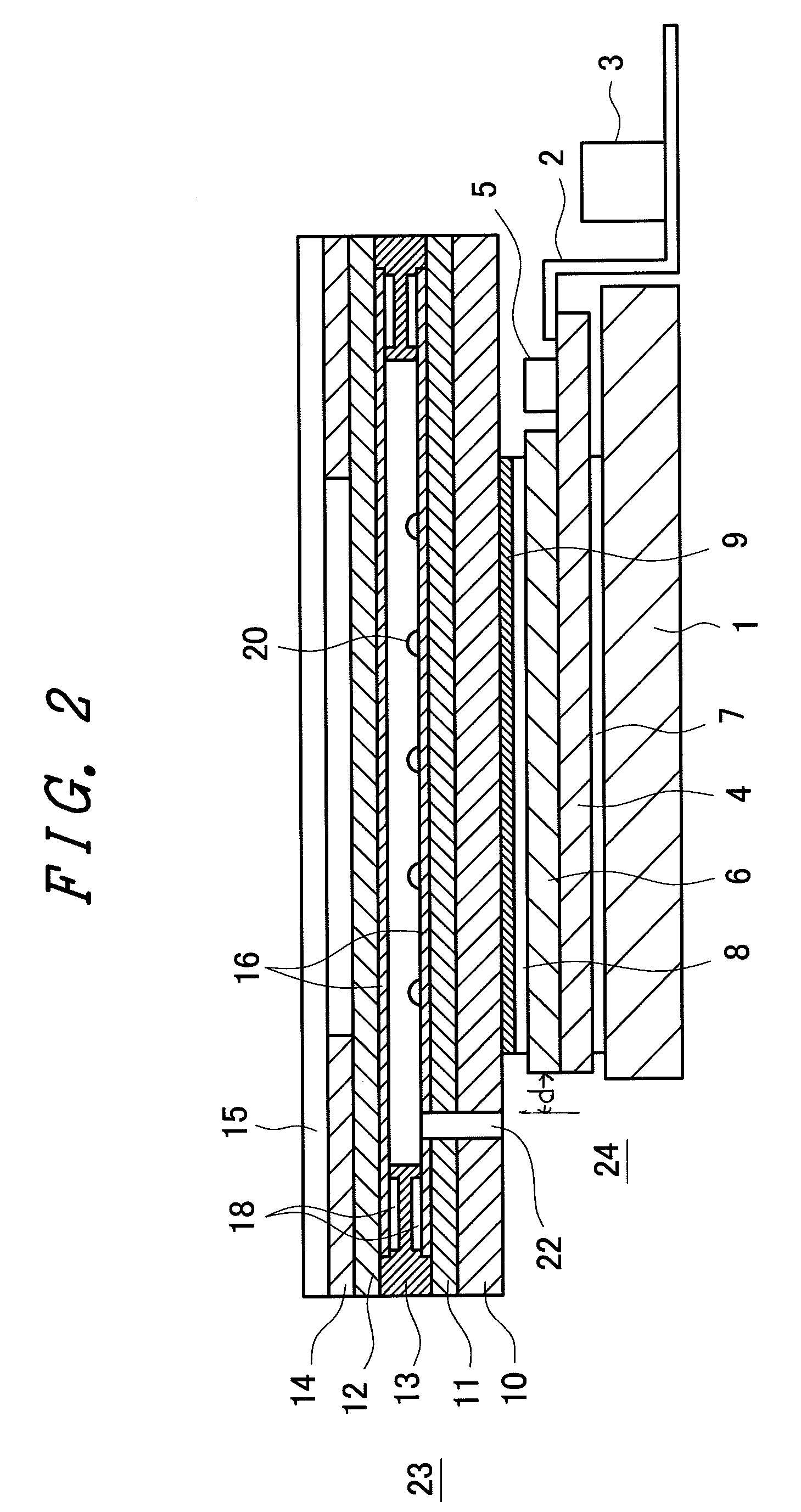
[0062]FIG. 6 is a cross-sectional view of a liquid crystal display device having a touch panel of the embodiment 2 according to the present invention. Most of the constitution of the liquid crystal display device shown in FIG. 6 is substantially equal to the constitution of the liquid crystal display device explained in the embodiment 1 in conjunction with FIG. 2. A point which makes the constitution shown in FIG. 6 different from the constitution shown in FIG. 2 lies in that air holes 22 formed in a lower transparent-electrode-attached film 11 and a base substrate 10 are closed. Although FIG. 6 shows an example in which the air holes 22 are closed by an adhesive tape 25, a material which closes the air holes is not limited to the adhesive tape 25, and the air holes 22 may be closed by a resin or the like. As such a resin, an epoxy resin, a silicon resin or the like is used.

[0063]In this manner, by closing the air holes 22, it is possible to prevent foreign materials from intruding ...

embodiment 3

[0066]In the touch panel 23, the upper transparent-electrode-attached film 12 and the lower transparent-electrode-attached film 11 are arranged to face each other in an opposed manner with a small distance therebetween. When the distance between the upper transparent-electrode-attached film 12 and the lower transparent-electrode-attached film 11 is decreased, there may be a case that a so-called Newton ring is generated with respect to a specific wavelength. The Newton ring causes lowers image quality and hence, it is necessary to prevent the generation of the Newton ring. By forming the air holes 22 in the touch panel 23, the pressure in the touch panel is lowered and hence, there may be a case that the upper transparent-electrode-attached film 12 is slackened. In this case, the distance between the upper transparent-electrode-attached film 12 and the lower transparent-electrode-attached film 11 is liable to become small. Although this slackening of the upper transparent-electrode-...


PUM

PropertyMeasurementUnit
Flexibilityaaaaaaaaaa
Transparencyaaaaaaaaaa
Refractive indexaaaaaaaaaa

Abstract

In a display device having a touch panel, it is possible to prevent the generation of a screen defect caused by the intrusion of air bubbles into a UV curing resin formed between a touch panel and a display panel. The touch panel is constituted of an upper transparent-electrode-attached film and a lower transparent-electrode-attached film, and an air hole is formed in the lower transparent-electrode-attached film. Due to such constitution, in adhering the touch panel and the display panel to each other in a vacuum using a UV curing resin, air in the touch panel is also discharged and hence, there is no possibility that the touch panel swells. Accordingly, it is possible to prevent warping of the lower transparent-electrode-attached film and hence, in curing the UV curing resin for adhering the touch panel and the display panel to each other, it is possible to prevent the entanglement of air into the UV curing resin. Accordingly, a touch-panel attached display device free from a screen defect attributed to air bubbles can be manufactured.

Description

CROSS-REFERENCE TO RELATED APPLICATIONS[0001]The disclosure of Japanese Patent Application No. 2007-249283 filed on Sep. 26, 2007 including the specification, drawings and abstract is incorporated herein by reference in its entirety.BACKGROUND[0002]1. Field of the Invention[0003]The present invention relates to a display device, and more particularly to a display device having a touch panel.[0004]2. Description of Related Arts[0005]Since a liquid crystal display device can be made small and thin, the application of the liquid crystal display device has been spreading to various fields. Mobile phones, PDA (personal digital assistant) and the like are examples of these fields. As such a liquid crystal display device, there has been known a liquid crystal display device of a type which uses a touch panel as an inputting device. Although various types of touch panels are known including an electrostatic-capacitance-type touch panel, a resistance-type touch panel and the like, the resist...

Claims


Application Information

Patent Timeline
IPC IPC(8): G06F3/041
CPCG02F1/13338G02F2202/28G02F2202/023G06F3/0412
Inventor MISHIMA, YASUYUKIKOBAYASHI, SETSUOHIGUCHI, TAKAYUKI
Owner PANASONIC LIQUID CRYSTAL DISPLAY CO LTD
Why Eureka
Try Eureka