Fluid ejecting apparatus and ejecting head maintenance method

a technology of ejecting apparatus and ejecting head, which is applied in the direction of printing, etc., can solve the problems of damage to the forming surface of the discharge port, damage to the discharge port forming surface,

Active Publication Date: 2009-03-26
SEIKO EPSON CORP
View PDF1 Cites 3 Cited by
  • Summary
  • Abstract
  • Description
  • Claims
  • Application Information

AI Technical Summary

Benefits of technology

[0022]By configuring as above, the cap member and the wiping member are controlled by the control portion, and the wiping processing, which is performed after every capping processing in known fluid ejecting apparatuses, is not performed after the capping processing is performed again. Therefore, thickened fluid can be prevented from being rubbed against the ejecting surface by the wiping member. In addition, the ejecting surface is prevented from being wiped without sufficient fluid thereon. Therefore, the ejecting surface can be prevented from being damaged by the wiping member. By controlling the cap member with the control portion and waiting a predetermined time after the capping processing is performed again, fluid attached to the vicinities of the ejecting ports in the ejecting surface can be sucked into the ejecting head through the ejecting ports due to the difference in pressure between inside and outside the ejecting head. Therefore, fluid on the ejecting surface can be removed without performing wiping processing. Consequently, fluid can be prevented from remaining on the ejecting surface and thickening.

Problems solved by technology

However, when a high-viscosity ink having a viscosity higher than that of known inks is used in the above known fluid ejecting apparatuses and ejecting head maintenance methods, at the time of cleaning, thickened ink is rubbed against the nozzles, thereby damaging the discharge-port forming surface.
This results in the absence of ink on the discharge-port forming surface at the time of cleaning, and the discharge-port forming surface is damaged by wiping.

Method used


Image

  • Fluid ejecting apparatus and ejecting head maintenance method
  • Fluid ejecting apparatus and ejecting head maintenance method
  • Fluid ejecting apparatus and ejecting head maintenance method

Examples


first embodiment

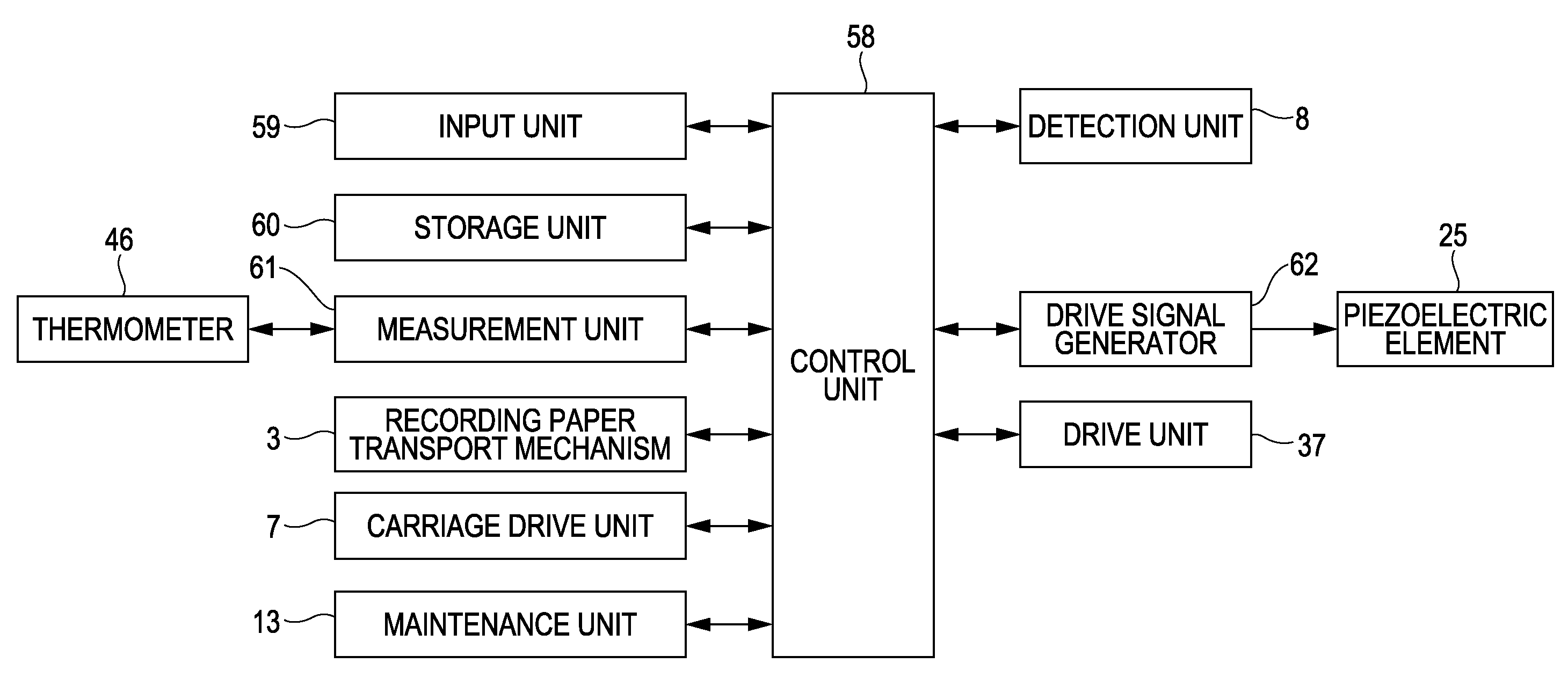
[0066]Next, a cleaning operation (maintenance method) of the ink jet printer 1 having the above-described structure will be described, focusing on the operation of the control unit 58, with reference to the flowchart of FIG. 8.

[0067]When cleaning is started (step S1), the control unit 58 activates the drive unit 37 to bring the upper end face of the cap member 34 into contact with the ejecting surface 17 (step S2). Next, the control unit 58 activates the maintenance unit 13, and suctions the fluid in the space formed between the cap member 34 and the ejecting surface 17 with the suction unit 35 (step S3). In this way, thickened ink in the ejecting ports 16 is discharged.

[0068]Next, the control unit 58 activates the drive unit 37, and takes the upper end face of the cap member 34 out of contact with the ejecting surface 17. Next, the control unit 58 activates the carriage drive unit 7 with the wiping member 44 set at a predetermined position, and wipes the ejecting surface 17 of the ...

second embodiment

[0074]Next, a cleaning operation of the ink jet printer 1 will be described with reference to the flowchart of FIG. 9. Since steps S1 to S8 of this cleaning operation are the same as those of the cleaning operation described above with reference to FIG. 8, the same reference numerals will be used to designate the same steps so that the description thereof will be omitted.

[0075]After performing the processing of steps S1 to S8, the control unit 58 detects the temperature of the thermometer 46 using the measurement unit 61 to measure the temperature of the recording head 4. Next, the control unit 58 stores the measured temperature of the recording head 4 in the storage unit 60. Next, the control unit 58 compares the stored measured temperature to a set temperature that is preset and stored in the storage unit 60 (step S21). When ink having the properties shown in FIG. 7 is used, the set temperature is preferably, for example, about 30° C. The reason is that when the temperature of the...

third embodiment

[0078]Next, a cleaning operation of the ink jet printer 1 will be described with reference to the flowchart of FIG. 10. This cleaning operation differs from the cleaning operation described above with reference to FIG. 9 in that step S31 is performed instead of step S21. Since the other steps are the same as those of the cleaning operation described above with reference to FIG. 9, the same reference numerals will be used to designate the same steps so that the description thereof will be omitted.

[0079]After performing the processing of steps S1 to S8, the control unit 58 calculates the elapsed time from the end of the last cleaning operation and the start of the present cleaning operation, using the measurement unit 61. Next, the control unit 58 stores the elapsed time in the storage unit 60 as a measured time. Next, the control unit 58 compares the stored measured time to a set time that is preset and stored in the storage unit 60 (step S31). The set time is preferably, for example...


PUM


Abstract

A method for maintaining a fluid ejecting apparatus including an ejecting head that has an ejecting surface in which a plurality of ejecting ports that eject fluid are formed, and a maintenance portion that performs maintenance processing to recover the ejection of fluid from the ejecting ports and that has a cap member and a wiping member. The method includes performing capping processing to put the cap member on the ejecting surface and to suck, and then wiping processing to wipe the ejecting surface with the wiping member, and performing the capping processing again and then waiting a predetermined time without performing the wiping processing.

Description

CROSS-REFERENCE TO RELATED APPLICATIONS[0001]This application is based upon and claims the benefit of priority from prior Japanese Patent Applications No. 2007-243838, filed on Sep. 20, 2007, the entire contents of which are incorporated herein by reference.BACKGROUND[0002]1. Technical Field[0003]The present invention relates to a fluid ejecting apparatus and an ejecting head maintenance method.[0004]2. Related Art[0005]There is known a fluid ejecting apparatus in which a cleaner such as a wiper is provided on a discharge-port forming surface of an ejecting head that ejects fluid. In addition, there is known an ejecting head maintenance method including wiping the discharge-port forming surface with a wiper, for example. As a technology for such apparatus and method, there is disclosed a technology to put a lid on nozzles with a small amount of ink flowing out thereof, to thereby eliminate concave meniscuses, to uniformly wet the lid, and to prevent air bubbles from entering the noz...

Claims


Application Information

Patent Timeline
Patent Type & Authority Applications(United States)
IPC IPC(8): B41J2/165
CPCB41J2/16535B41J2/16523
Inventor FUKASAWA, SHIGENORIHOSONO, SATORUOKUMURA, HIDEKITOJO, SEIJI
Owner SEIKO EPSON CORP
Why Eureka
Try Eureka