Switching power supply

a power supply and power supply technology, applied in the field of switching power supply, can solve problems such as inability to operate, and achieve the effect of minuteness of signal used

Active Publication Date: 2009-03-26
FUJI ELECTRIC CO LTD
View PDF9 Cites 29 Cited by
  • Summary
  • Abstract
  • Description
  • Claims
  • Application Information

AI Technical Summary

Benefits of technology

[0021]A switching power supply of this invention superimposes an added slope signal in an early stage of a rise of a current detection signal, so that even when a load is light and a switching frequency is high, by causing a combined signal Vsig to reach a certain magnitude, an output FB of an error amplifier ERRAMP which is balanced with this is also increased, and even in a current mode, causes of unstable operation arising from the minuteness of the signal used to generate PWM signals can be eliminated.

Problems solved by technology

Further, because the feedback signal FB, which is the output of the error amplifier ERRAMP, is minute, the signal is readily affected by noise, and this also gives rise to unstable operation.

Method used


Image

  • Switching power supply
  • Switching power supply
  • Switching power supply

Examples


Embodiment Construction

[0036]Below, a switching power supply of the invention is explained using the drawings.

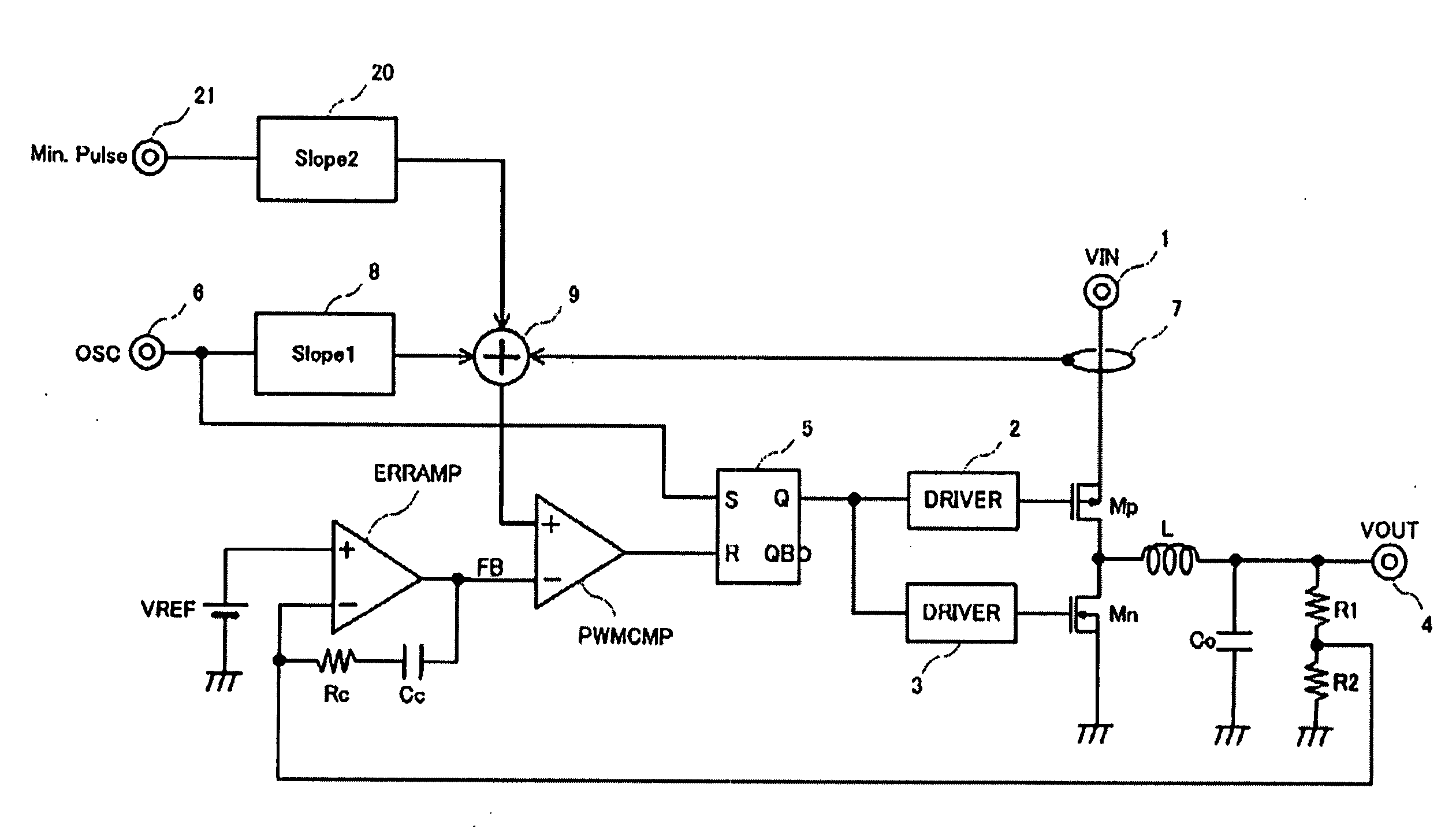
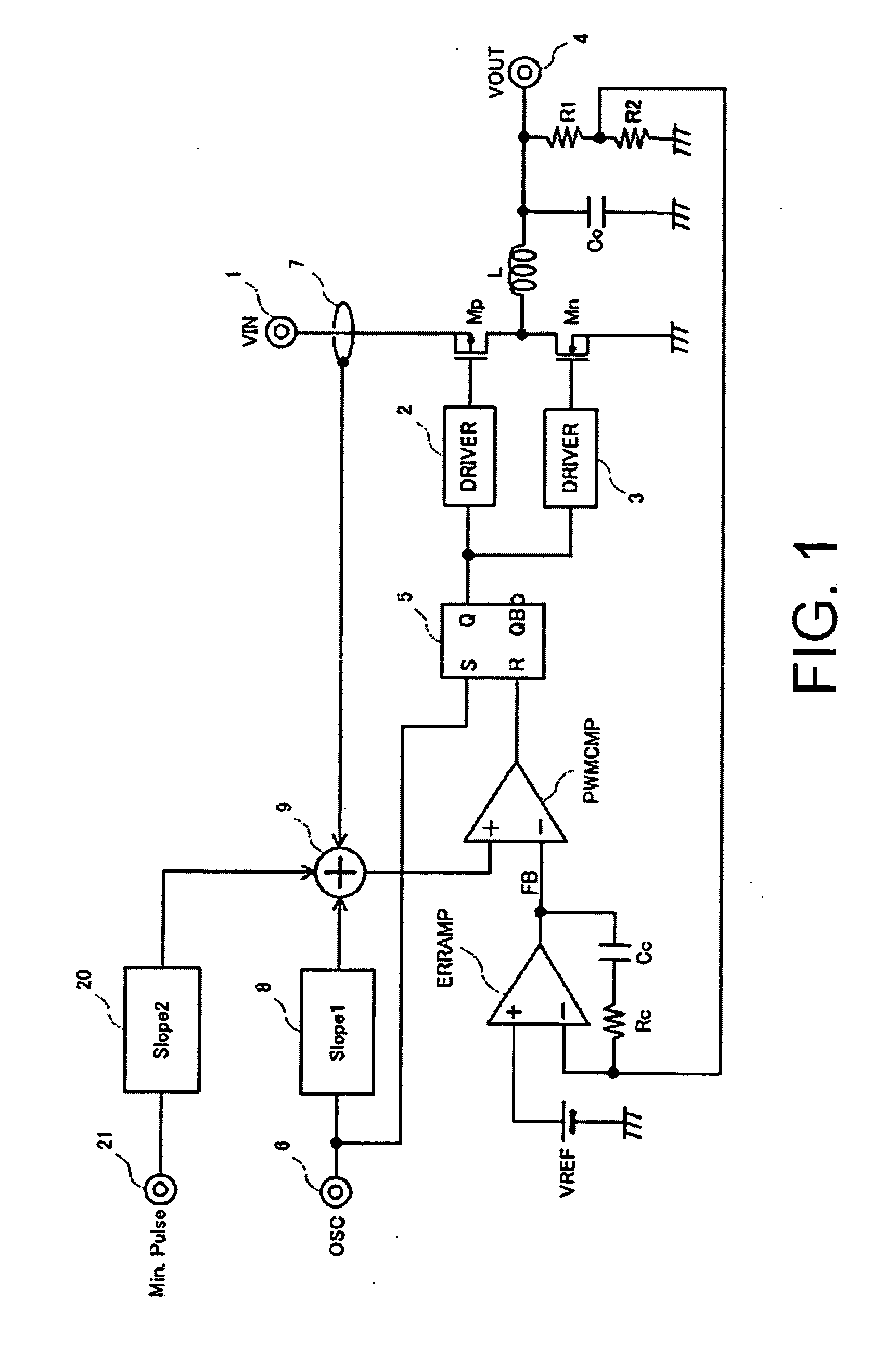
[0037]FIG. 1 shows an example of an overall configuration of a switching power supply of the invention. Portions which are the same as in FIG. 11 are assigned the same symbols, and detailed explanations are omitted. Differences of this embodiment with the switching power supply shown in FIG. 11 are the provision of an added slope circuit 20, and the use of an added slope signal which is the output thereof as a third input signal to the adder circuit 9. A signal Min. Pulse is input to the added slope circuit 20 from an input terminal 21. A monotonically increasing signal is generated over an interval specified by the signal Min. Pulse, and this signal is input to the adder circuit 9 as the added slope signal. The signal Min. Pulse has a same frequency as a signal OSC (that is, the same frequency as the switching frequency), and is a synchronized signal; when a new period of the signal OSC begins, t...


PUM


Abstract

A current-mode switching power supply is provided, in which there is no unstable operation arising from the fact that signals to generate PWM signals are minute, even when a load is light and a switching frequency is high. In a switching power supply of this invention, an added slope signal is superposed in an early stage of a rise of a current detection signal, so that a combined signal Vsig is caused to reach a certain magnitude even when the load is light and the switching frequency is high, and consequently an output FB of an error amplifier ERRAMP which is balanced with the combined signal is also increased. By this means, even in a current mode, it is possible to eliminate unstable operation arising from the fact that the feedback signal FB which is the output of the error amplifier ERRAMP and the combined signal Vsig are minute.

Description

BACKGROUND OF THE INVENTION[0001]1. Field of the Invention[0002]This invention relates to a-current-mode switching power supply.[0003]2. Description of the Related Art[0004]FIG. 11 is a block diagram of an example of a current-mode switching power supply of the prior art. Here 1 is an input terminal, to which the input voltage VIN of the switching power supply is input; Mp is a P-channel MOS transistor, which is a switching element; Mn is an N-channel MOS transistor, which is a synchronous rectifying element; and the two transistors Mp and Mn are driven by respective driving circuits 2 and 3 so as to be turned on and off in alternation. A smoothing filter, comprising a series circuit of an inductor L and output capacitor Co, is connected to the connection point of the transistors Mp and Mn. By turning on and off in alternation the transistors Mp and Mn connected to the input voltage VIN, the intermittent voltage occurring at the connection point is smoothed by the smoothing circuit ...

Claims


Application Information

Patent Timeline
Patent Type & Authority Applications(United States)
IPC IPC(8): H02M7/155
CPCH02M3/156
Inventor NAKAHASHI, YASUNORI
Owner FUJI ELECTRIC CO LTD
Why Eureka
Try Eureka