Portable electric drill with directional indicators

a portable, electric drill technology, applied in the direction of portable power-driven tools, drilling/boring measurement devices, manufacturing tools, etc., can solve the problems of alternating current powered tools, limited time for operation of battery-powered tools, and high cost of battery-powered tools, so as to prevent damage to drill bits, prolong battery life, and finish work

Inactive Publication Date: 2009-03-26
INNOVATIVE CONCEPTS
View PDF5 Cites 23 Cited by
  • Summary
  • Abstract
  • Description
  • Claims
  • Application Information

AI Technical Summary

Benefits of technology

[0008]It will be understood that the prevention of such rotation inadvertently in the wrong direction will be effective to preserve battery life and prevent damage to drill bits, finished work and the like.

Problems solved by technology

First of all, these battery-powered tools may only be operated for a limited amount of time.
In addition, batteries, while they do provide efficiency of effort as compared to conventional alternating current powered tools, do involve considerable expense.
In addition, proper disposal of the batteries carries added costs.
In connection with this, it is also noted that rechargeable batteries do have a limited life in terms of the number of times which they may be recharged.
More particularly, reversible drills of the battery powered variety may, by mistake, be powered with a drill bit going in the wrong direction.
This results in loss of power and depletion of battery life.
Many times, this may occur for a prolonged period of time and is only discovered when the lack of progress, for example, in drilling a hole, becomes apparent.
In addition, operation of a drill in reverse against the workpiece may cause a drill bit to overheat.
If a screw or bolt is properly seated in a workpiece and it is desired to unscrew it, operation in the forward direction may cause it to strip threads cut in the workpiece.
However, markings may be difficult to read, and with time, may chip away.
In addition, such markings are typically on or adjacent to the drill actuation switch and are thus not easily visible, because of their position, and may even be covered by the fingers of the individual using the battery-powered drill.

Method used


Image

  • Portable electric drill with directional indicators
  • Portable electric drill with directional indicators
  • Portable electric drill with directional indicators

Examples


Embodiment Construction

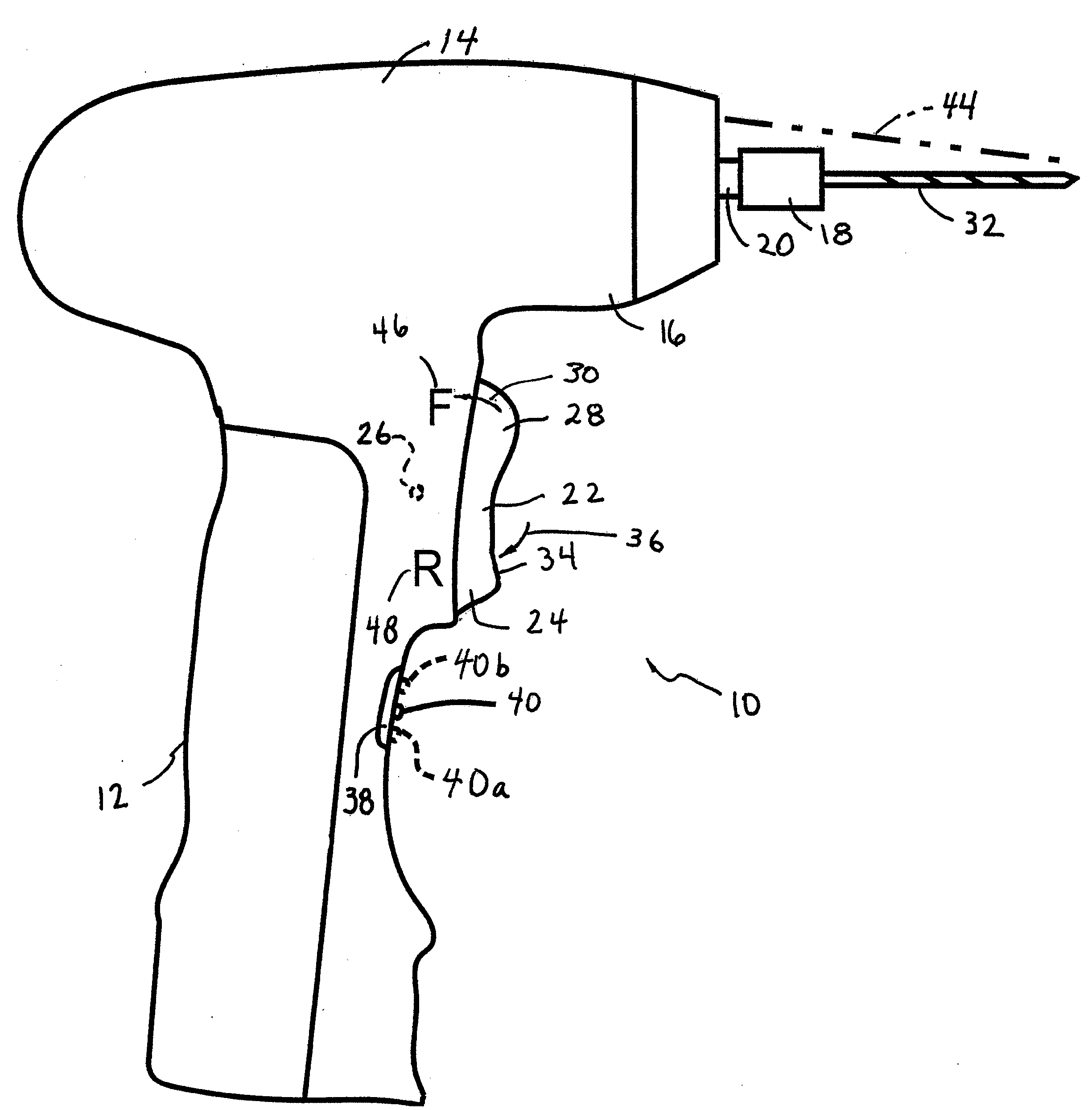
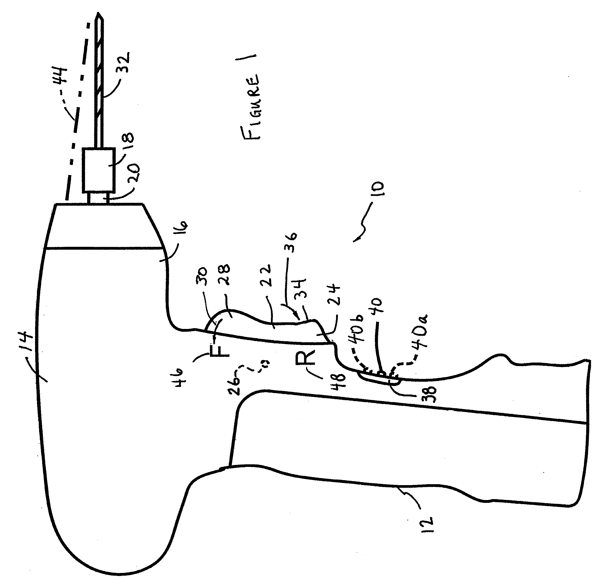
[0028]Referring to FIGS. 1-4, an electric drill 10 incorporating a directional indicator is illustrated. Drill 10 also incorporates a battery testing configuration in accordance with the present invention. Drill 10 includes a handle portion 12 and a driver portion 14. Driver portion 14 comprises a neck 16.

[0029]A chuck 18, of conventional design, is mounted on a spindle 20. In accordance with the preferred embodiment, it is contemplated that chuck 18 may be any conventional hex socket chuck, as a wide variety of tool bits having mountings suitable for such chucks are readily available on the market.

[0030]Other chuck configurations, for example, a multi-fingered chuck, for example one of the type using a serrated sleeve may be employed. Alternatively, a multi-fingered chuck employing a conical gear pin key (such as that sold by Jacobs Manufacturing) may also be advantageously employed in accordance with the present invention.

[0031]Spindle 20 is coupled to a motor, not illustrated, bu...


PUM

PropertyMeasurementUnit
charge stateaaaaaaaaaa
state of chargeaaaaaaaaaa
coloraaaaaaaaaa

Abstract

In accordance with the invention, a drill comprises a drill housing with a handle portion and a driver portion. An electrical drill motor is located in the driver portion. The drill motor has an output shaft for coupling output rotary power. An electrical switch controls the operation of the drill motor. The electrical switch it is located on the handle portion of the drill housing. A chuck is coupled to the output shaft of the drill motor. Directional indicators show drill direction and cooperate with a charge state indicator positioned not to be accidentally actuated to maximize power efficiency.

Description

CROSS REFERENCE TO RELATED APPLICATIONS[0001]This application is a continuation-in-part of application Ser. No. 11 / 505,014, the disclosure of which is incorporated herein by reference.TECHNICAL FIELD[0002]The invention relates to efficiency promoting features in portable drills powered by batteries, such as rechargeable batteries.STATEMENT REGARDING FEDERALLY SPONSORED RESEARCH OR DEVELOPMENT[0003]Not applicable.BACKGROUND OF THE INVENTION[0004]Electrically powered drills remain one of the mainstays of every tool box, whether it be that of a homeowner or construction professional. Even going back to the 1950s, electrical drills were in very common use in the home, with companies like Sears Roebuck & Co. and others turning out high quality products at modest prices in what was then a very old technology.[0005]Indeed, the most modern form of the electric drill, namely a pistol shaped device with a multi-fingered chuck that could be tightened using a conical gear key, followed closely ...

Claims


Application Information

Patent Timeline
Patent Type & Authority Applications(United States)
IPC IPC(8): B23B49/00
CPCB25B21/00Y10T408/21B25F5/021B25B23/18
Inventor CANINO, SERAFINOGELORMINO, SCOTT
Owner INNOVATIVE CONCEPTS
Why Eureka
Try Eureka