
Transmission power control method and apparatus

a power control and power technology, applied in power management, transmission monitoring, multiplex communication, etc., can solve problems such as failure of data transmission and reception, inability to measure the received bler in a section, and inability to perform appropriate update of the targ

Inactive Publication Date: 2009-03-26
NTT DOCOMO INC
View PDF11 Cites 17 Cited by
  • Summary
  • Abstract
  • Description
  • Claims
  • Application Information

AI Technical Summary

Benefits of technology

[0024]The present invention is implemented to solve the foregoing problems. Therefore it is an object of the present invention to provide a transmission power control method whose processing load is light, whose trackability to the changes in environments is high, and which can maintain the communication quality at a prescribed quality even in the absence of the received data in the dedicated physical data channel (DPDCH).
[0027]In the transmission power control method in accordance with the present invention, the receiver can have a movement speed detecting function; and the step of generating the command for controlling the transmission power of the transmitter of the first channel can be halted when the user data is not received via the first channel, and the movement speed of the receiver detected by the detecting function is a particular fixed speed or more.
[0030]In the receiver in accordance with the present invention, the means for generating the command for controlling the transmission power of the transmitter of the first channel can decide an amount of update of the target SIR in response to a magnitude of difference between the received quality of the second channel at a time when user data reception from the transmitter via the first channel is stopped and the current received quality of the second channel.
[0032]In the receiver in accordance with the present invention, the receiver can have movement speed detecting means; and the means for generating the command for controlling the transmission power of the transmitter of the first channel can adjust the amount of update of the target SIR in response to the movement speed of the receiver detected by the detecting means.
[0034]In addition, as compared with the case of using the quality of the dedicated physical data channel, it can increase the trackability to the changes in environments with holding down the processing load.
[0036]Even if the receiver moves from a high quality environment (in which the BER of a dedicated channel is nearly zero) to a higher quality environment, the quality of the dedicated channel is unchanged superficially. The receiver in accordance with the second aspect of the present invention can easily make a decision as to the changes in the environment with a comparison with the quality at a time when the transmission and reception of the user data halts. Thus, it can control in such a manner as not to require excessive (more than necessary) quality in such a quality environment.

Problems solved by technology

Here, when the transmitter transmits the user data to the receiver intermittently, that is, when the receiver receives the received data (user data or packet data) intermittently via the DPDCH, it cannot measure the received BLER in a section where the user data is not received because of the lack of the data to be measured.
However, the outer-loop control using a fixed value as the target SIR in the transmitted and received data-less section presents a problem of causing a failure of the data transmission and reception because of not requiring power in spite of the degradation in quality, or a problem of requiring power even if the quality is good enough.
However, the long time averaging, which has a tendency to deteriorate the trackability to the changes in environments, has a problem of being unable to perform appropriate update of the target SIR when the environments change suddenly.
Besides, as for the method (re-encoding method) of calculating the BER approximately by re-encoding the data passing through the error correction decoding, and by carrying out bit-by-bit comparison with the received data before the error correction decoding, it has a problem in that the processing load is heavy in addition to the problem of an error due to uncorrected bits.

Method used


Image

  • Transmission power control method and apparatus
  • Transmission power control method and apparatus
  • Transmission power control method and apparatus

Examples


Embodiment Construction

[0061]The embodiments in accordance with the invention will now be described with reference to the accompanying drawings.

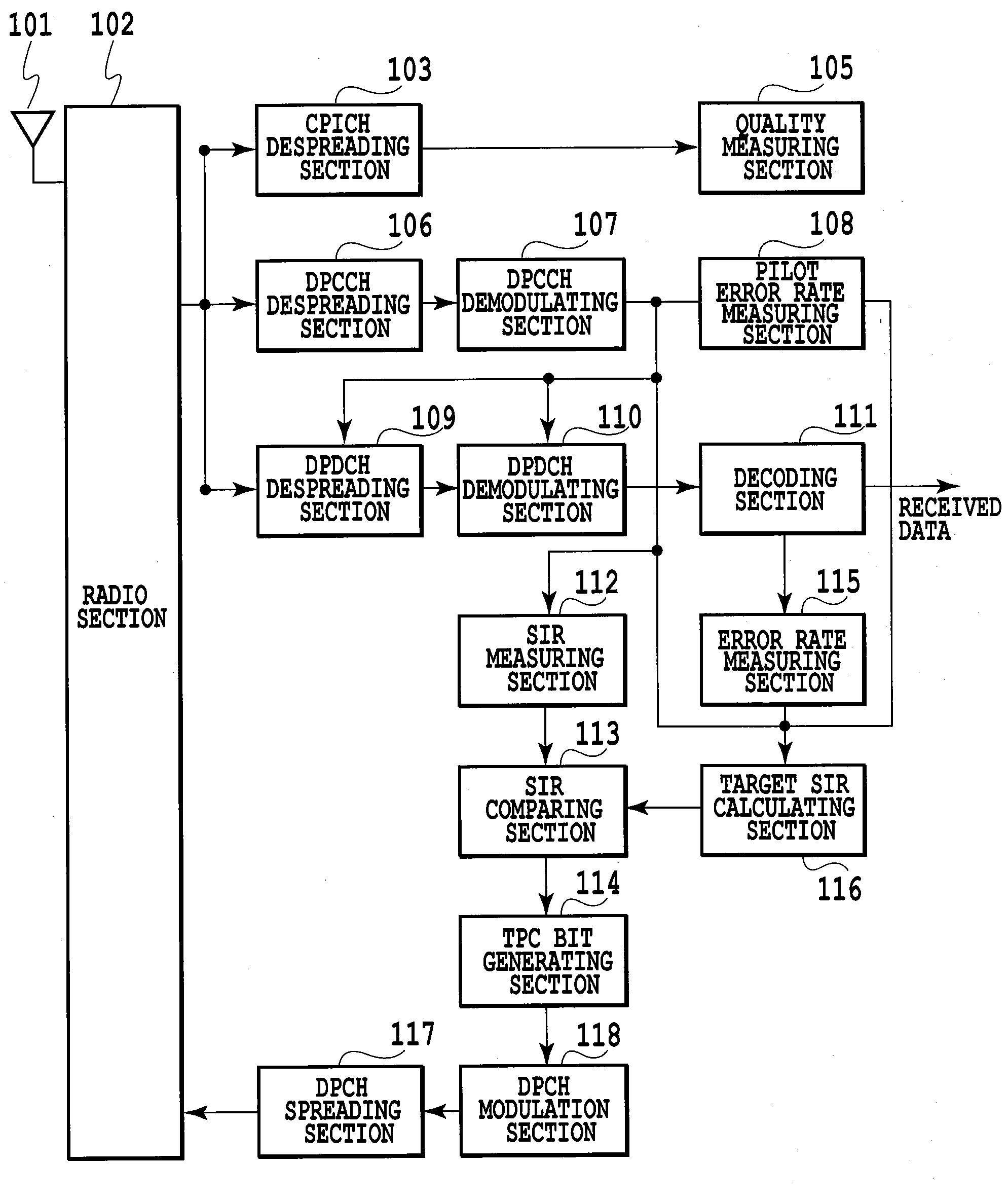
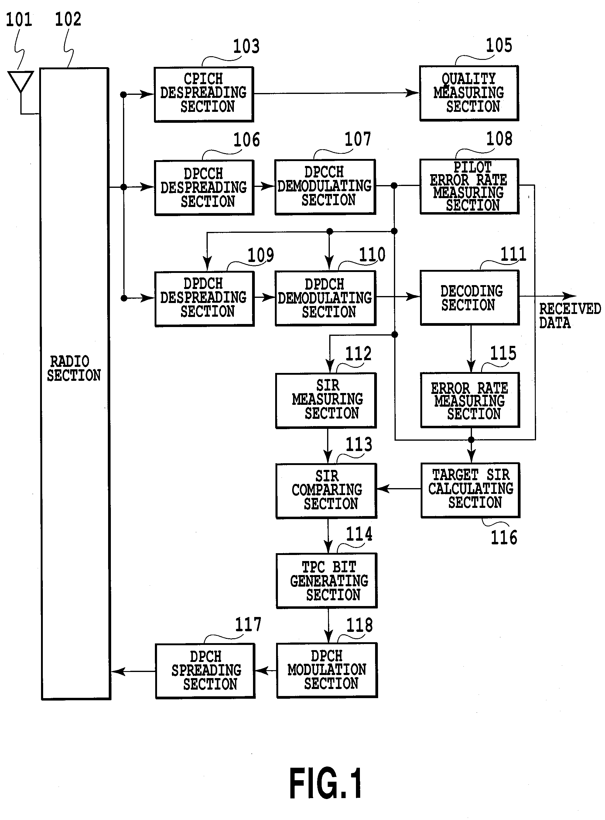
[0062]FIG. 3 shows a configuration of a mobile station of an embodiment in accordance with the present invention. A radio section 102 performs prescribed receiving processing such as frequency conversion of the signal (received signal) received by an antenna 101. In addition, the radio section 102 performs prescribed transmission processing such as frequency conversion of a DPCH signal from a DPCH spreading section 117 which will be described later, and transmits the DPCH signal passing through the transmission processing via the antenna 101.

[0063]A CPICH despreading section 103 despreads the received signal passing through the receiving processing by the radio section 102 by using a spread code assigned to a common pilot channel (CPICH). A quality measuring section 305 measures received quality (such as a received error rate (BER), a received EC / NO (energy per ca...


PUM


Abstract

In a transmission power control method, a receiver receives user data transmitted intermittently from a transmitter to a receiver and control data transmitted continuously from the transmitter to a plurality of receivers including the receiver via a DPDCH and a CPICH, respectively; and generates, when the receiver is receiving the user data from the transmitter via the DPDCH, a command for controlling transmission power of the transmitter of a DPDCH in a manner that an SIR of a received signal of the DPDCH by the receiver becomes equal to a target SIR, and generates, when the receiver is not receiving the user data from the transmitter via the DPDCH, a command for controlling the transmission power of the transmitter of the DPDCH by updating the target SIR by using received quality of the CPICH.

Description

TECHNICAL FIELD[0001]The present invention relates to a transmission power control method and apparatus between a transmitter and a receiver (mobile station) for carrying out radio data communication.BACKGROUND ART[0002]Conventionally, a W-CDMA communications system performs transmission power control for maintaining the communication quality of a dedicated physical channel (DPCH) at a prescribed level.[0003]The transmission power control sometimes performs closed-loop transmission power control in a dual-loop structure of inner-loop control and outer-loop control to maintain stable communication quality under various environments. In this case, the inner-loop control instructs the opposite transmitter to increase or decrease the transmission power to adjust the signal to interference ratio (received SIR) of the radio signal (DPCCH signal) received by the receiver to a target signal to interference ratio (target SIR) as close as possible; and the outer-loop control increases or decr...

Claims


Application Information

Patent Timeline
Patent Type & Authority Applications(United States)
IPC IPC(8): H04B7/00H04B1/707H04J13/00H04W52/04H04W52/12H04W52/44
CPCH04B1/707H04W52/143H04W52/44H04W52/282H04W52/241H04W52/24
Inventor IWANAGA, MITSUOOKUMURA, YUKIHIKOOKAMOTO, ETSUHIRO
Owner NTT DOCOMO INC
Learn More