Device and Method for Encoding by Principal Component Analysis a Multichannel Audio Signal

a multi-channel audio and principal component technology, applied in the field of coding by principal component analysis of multi-channel audio signals, can solve the problem of insufficient energy of the signals coming from this analysis in the principal component, and achieve the effect of improving the audio quality of the decoded signals

Active Publication Date: 2009-03-26
FRANCE TELECOM SA
View PDF7 Cites 17 Cited by
  • Summary
  • Abstract
  • Description
  • Claims
  • Application Information

AI Technical Summary

Benefits of technology

[0070]In a manner so as to obtain components decorrelated from one another, the decoder uses, by default, an all-pass filter known as a decorrelation filter. Whereas a reverberation filter is used in the documents WO 03 / 085643 and WO 03 / 085645, the present invention proposes a switching between a decorrelation filter and a reverberation filter only when the analysis of the signals carried out at the encoding has detected the presence of reverberation in the original signals. Indeed, only an index is calculated at the encoder and transmitted for each frame processed so as to inform the decoder of the type of filter to be used. This switching between the filters to be used then allows reverberation of the signals, which are not originally reverberating, to be avoided and therefore the audio quality of the decoded signals to be improved.

Problems solved by technology

However, the PCA carried out according to the prior art does not allow a precise characterization of the signals to be coded and, consequently, the energy of the signals coming from this analysis is not compacted enough in the principal component.

Method used


Image

  • Device and Method for Encoding by Principal Component Analysis a Multichannel Audio Signal
  • Device and Method for Encoding by Principal Component Analysis a Multichannel Audio Signal
  • Device and Method for Encoding by Principal Component Analysis a Multichannel Audio Signal

Examples


Embodiment Construction

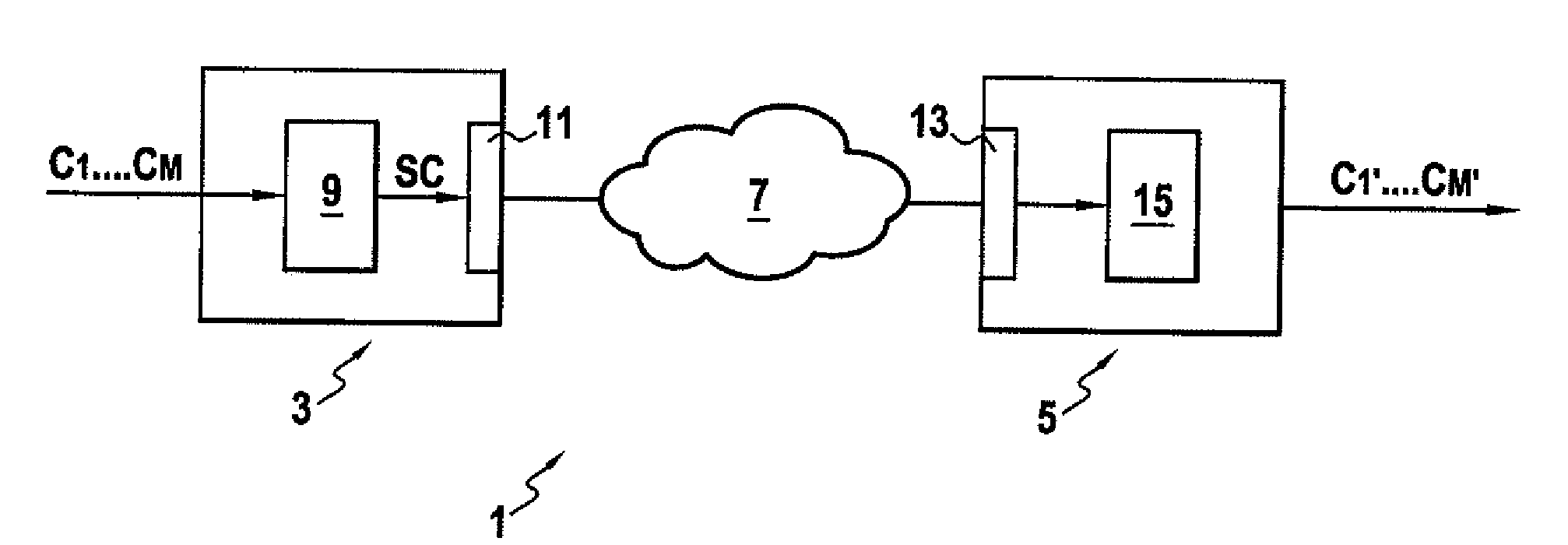
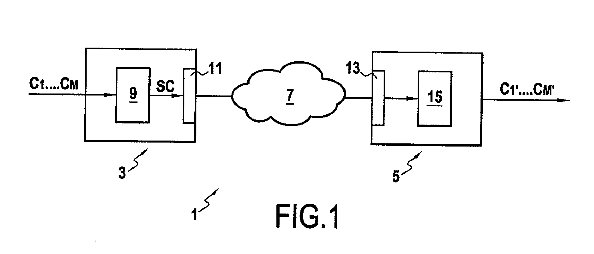
[0080]According to the invention, FIG. 1 is a schematic view of a communications system 1 comprising a coding device 3 and a decoding device 5. The coding 3 and decoding 5 devices can be connected together by means of a communications network or line 7.

[0081]The coding device 3 comprises an encoder 9 which, upon receiving a multi-channel audio signal C1, . . . ,CM generates a coded audio signal SC representative of the original multi-channel audio signal C1, . . .,CM.

[0082]The encoder 9 can be connected to a means of transmission 11 in order to transmit the coded signal SC via the communications network 7 to the decoding device 5.

[0083]The decoding device 5 comprises a receiver 13 for receiving the coded signal SC transmitted by the coding device 3. In addition, the decoding device 5 comprises a decoder 15 which, upon receiving the coded signal SC, generates a decoded audio signal C′1, . . . ,C′M corresponding to the original multi-channel audio signal C1, . . . ,CM.
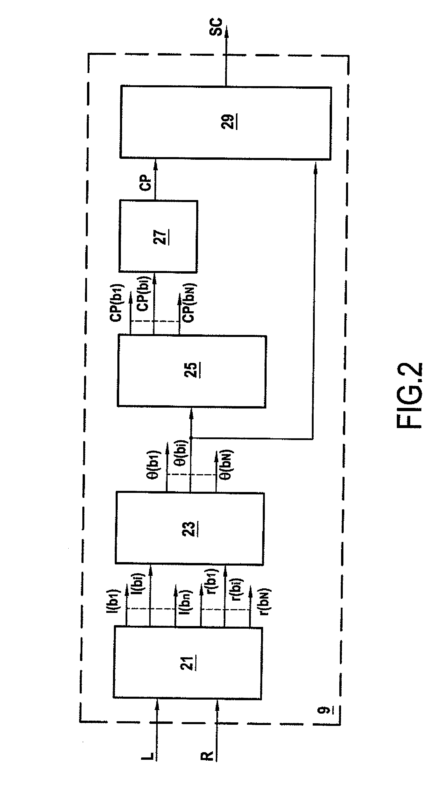
[0084]FIG. 2 is ...


PUM


Abstract

A system and a method for coding by principal component analysis (PCA) of a multi-channel audio signal comprising the following steps: decomposing at least two channels (L, R) of said audio signal into a plurality of frequency sub-bands (1(b1), . . . , 1(bN), r(b1), . . . , r(bN)), calculating at least one transformation parameter (θ(b1), . . . , θ(bN)) as a function of at least some of said plurality of frequency sub-bands, transforming at least some of said plurality of frequency sub-bands into a plurality of frequency sub-components as a function of said at least one transformation parameter (θ(b1), . . . , θ(bN)), said plurality of frequency sub-components comprising principal frequency sub-components (CP(b1), . . . , CP(bN)), combining at least some of said principal frequency sub-components (CP(b1), . . . , CP(bN)) in order to form a principal component (CP), and defining a coded audio signal (SC) representing said multi-channel audio signal (C1, . . . ,CM), said coded audio signal (SC) comprising said principal component (CP) and said at least one transformation parameter (θ(b1), . . . , θ(bN)).

Description

FIELD OF THE INVENTION[0001]The invention relates to the field of coding by principal component analysis of a multi-channel audio signal for audio-digital transmissions over various transmission networks at various data rates. More particularly, the aim of the invention is to allow low-data-rate transmission of multi-channel audio signals of the stereophonic (2 channels) or 5.1 (6 channels) type or others.BACKGROUND OF THE INVENTION[0002]In the framework of the coding of multi-channel audio signals, two approaches are particularly well known and used.[0003]The first and oldest consists in matrixing the channels of the original multi-channel signal in such a manner as to reduce the number of signals to be transmitted. By way of example, the Dolby® Pro Logic® II multi-channel audio coding method carries out the matrixing of the six channels of a 5.1 signal into two signals to be transmitted. Several types of decoding can be applied in order to reconstruct as faithfully as possible the...

Claims


Application Information

Patent Timeline
Patent Type & Authority Applications(United States)
IPC IPC(8): G10L19/00G10L19/008
CPCG10L19/008G10L19/02H03M7/30H04N21/233
Inventor BRIAND, MANUELVIRETTE, DAVID
Owner FRANCE TELECOM SA
Why Eureka
Try Eureka