Jetting apparatus and origin correction method therefor

a technology of origin correction and jetting apparatus, which is applied in the direction of process and machine control, program control, instruments, etc., can solve the problems of accuracy deviation for every operator, error at a processing top point, and difficulty in narrowing the tolerance range of the nozzle, so as to achieve stable jetting accuracy

Inactive Publication Date: 2009-04-02
SUGINO MACHINE
View PDF2 Cites 29 Cited by
  • Summary
  • Abstract
  • Description
  • Claims
  • Application Information

AI Technical Summary

Benefits of technology

[0022]In accordance with the jetting apparatus and the origin correction method in the jetting apparatus according to the invention, it is possible to ensure stable jetting accuracy.

Problems solved by technology

However, compared to the conventional three-axis control, when performing controls of not less than five axes accompanied with an axis rotation control, if there exists any of a nozzle-jet-outlet positional displacement and a nozzle center-axis tilt (angularity), there occurs an error at a position of a processing top point, depending on a rotation angle when a control axis is rotated (tilted or pivoted).
Accordingly, when performing the controls of not less than five axes, there exists a problem that it becomes burdensome to adjust a machine origin position of each axis and that there occurs an accuracy deviation for every operator.
On the other hand, it is difficult to narrow a tolerance range of a nozzle and to ensure accuracy, and there exists a fear that the accuracy varies every time when the nozzle is changed.
Therefore, because processing accuracy of the nozzle has to be measured every time when the nozzle is changed, a correction parameter has to be input, based on the measured value of the nozzle, and then a machine origin has to be corrected, there exists a problem that a measurement error occurs and an operation time is longer.

Method used


Image

  • Jetting apparatus and origin correction method therefor
  • Jetting apparatus and origin correction method therefor
  • Jetting apparatus and origin correction method therefor

Examples


Embodiment Construction

[0029]Here will be described an embodiment of the present invention in detail with reference to drawings as needed.

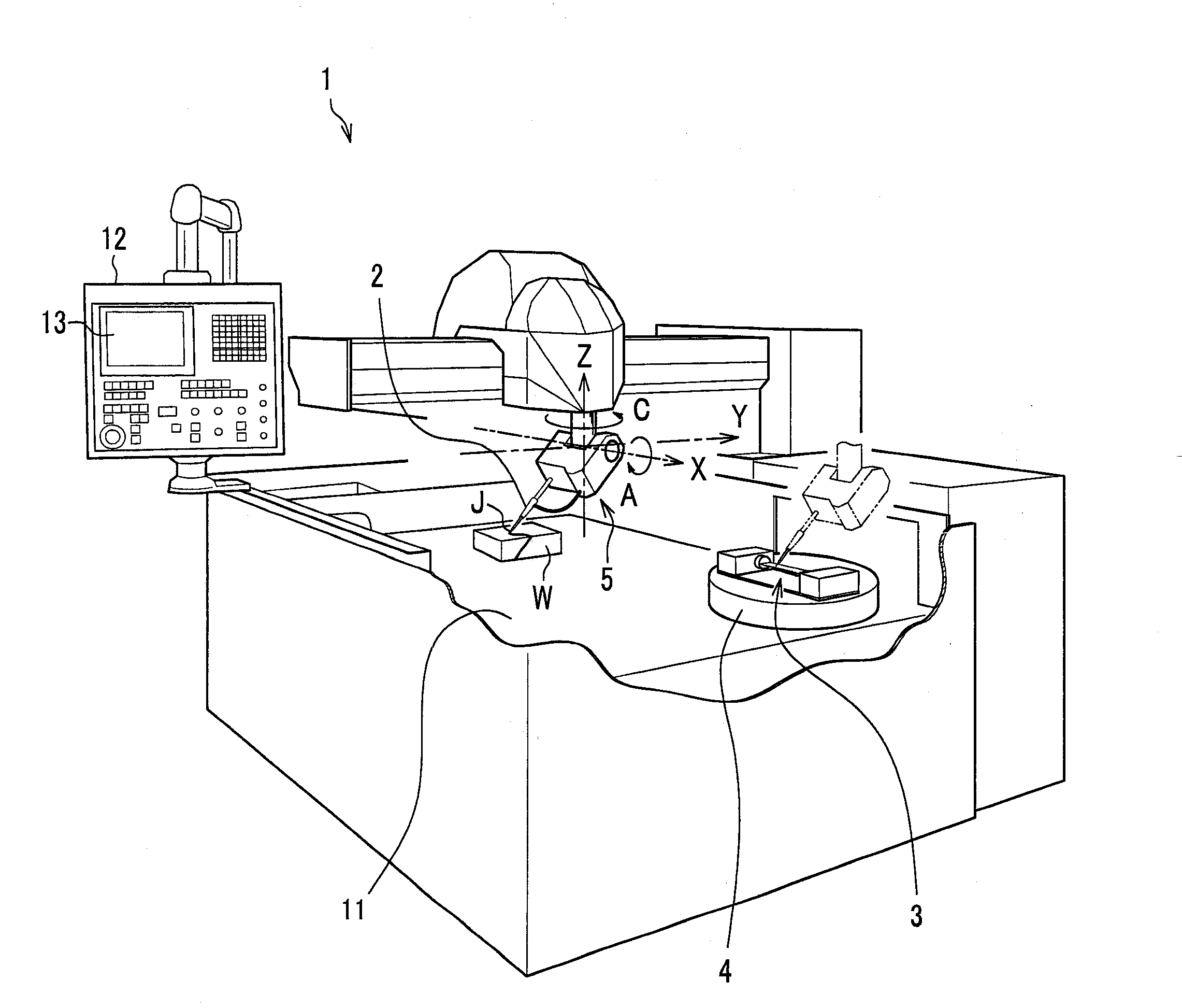
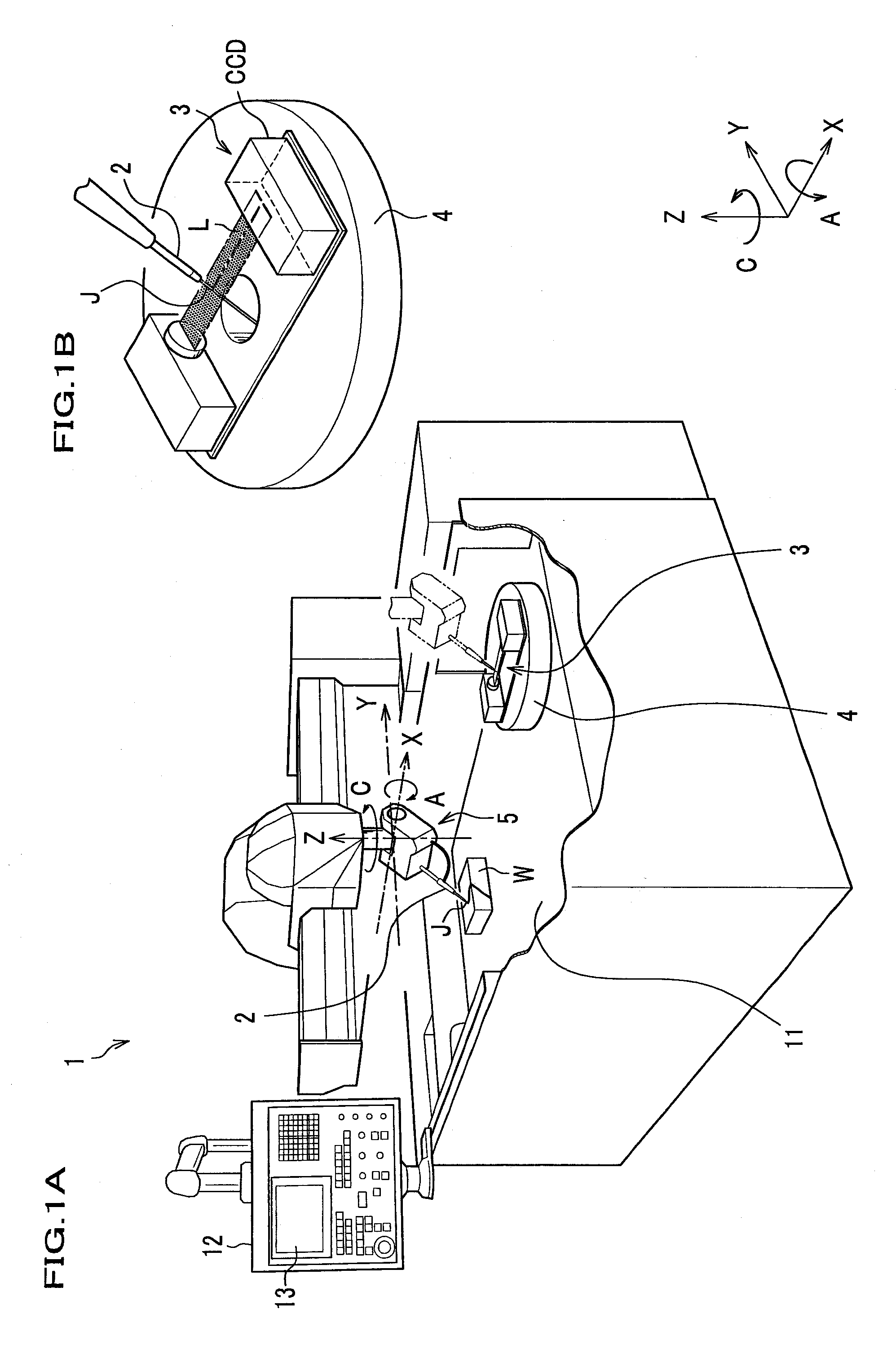
[0030]A jetting apparatus 1 according to the embodiment of the invention comprises, as shown in FIG. 1A: a two-axis angle control (A axis, C axis) for controlling a tilt angle and a pivot angle other than a three-axis control consisting of an X-axis and a Y-axis orthogonalized with each other and a Z-axis of a spray axis line; a nozzle 2 for spraying a high pressure fluid (for example, water) (jet J) of a high pressure jet flow on a work W; a high pressure fluid (for example, water) supply device (not shown) for supplying the high pressure water to the nozzle 2; an origin correction controller (not shown) for matching a processing top point stored and set in a control unit with a machine top point of the jet J sprayed; and a laser sensor 3 of an optical size-measurement device placed on a rotation table 4; and an operation panel 12 operated by an operator.

[0031]Meanwhil...


PUM

PropertyMeasurementUnit
tilt angleaaaaaaaaaa

Abstract

An origin correction method of matching a set processing top point with a machine top point of a high pressure jet in a jetting apparatus having a two-axis angle control for controlling tilt and -pivot angles other than a three-axis control consisting of X, Y, Z-axes includes: a jet radial-runout measurement process of measuring a position of the jet passing through an XY-plane; a jet radial-runout correction process of calculating an error at the processing top point and correcting radial runout of the jet; a jet top-point variation measurement process of changing the tilt angle and measuring two positions, where the jet passes through the XY-plane; and a jet top-point variation correction process of calculating an error at the processing top point from position data of the two positions and correcting a deviation of the processing top point.

Description

[0001]This application claims the foreign priority benefit under 35 U.S.C. §119 of Japanese Patent Application No. 2007-254305 filed on Sep. 28, 2007, the disclosure of which is incorporated herein by reference.BACKGROUND OF THE INVENTION[0002]1. Field of the Invention[0003]The present invention relates to a jetting apparatus and an origin correction method therefor, and particularly, to a jetting apparatus and an origin correction method for the apparatus that can ensure stable processing accuracy.[0004]2. Description of the Related Art[0005]Water jetting by a jetting apparatus sprays pressurized water at a speed of not less than twice of a sound speed and performs processing. Therefore, because the water jetting can perform shaping such as cutting while avoiding an influence on a property of a work without generating heat, it is suitable for processing a new material, without selecting a material, and the application of the water jetting has been broadened to various fields.[0006]...

Claims


Application Information

Patent Timeline
Patent Type & Authority Applications(United States)
IPC IPC(8): B26D5/00
CPCB26D3/10B26D5/005B26D5/007B26D7/2628G05B2219/50142B26F3/004G05B19/404G05B2219/49012G05B2219/50033B26F1/3806Y10T83/141
Inventor KATA, AKIRATERASAKI, NAOTSUGUAOKI, TAKUYA
Owner SUGINO MACHINE
Why Eureka
Try Eureka