
Molded modular cable dunnage system

a modular cable and cable dunnage technology, applied in the field of electrical wire and cable, can solve the problems of untanglement, damage to materials, waste of valuable time and resources, etc., and achieve the effects of avoiding the use of traditional spools or reels, and avoiding waste of resources

Inactive Publication Date: 2009-04-02
AISTON CHRISTOPHER J +1
View PDF8 Cites 19 Cited by
  • Summary
  • Abstract
  • Description
  • Claims
  • Application Information

AI Technical Summary

Benefits of technology

[0010]In a third aspect, methods for assembling modular dunnage systems are provided. Preferably, such methods include the steps of providing a hollow bolt having a first end and a second end, wherein a stop is connected to the first end of the hollow bolt, and orienting the hollow bolt vertically with the stop facing down; providing a first reel-hub half and a second reel-hub half, each reel-hub half having a flange portion, a hub portion having a flange end and a terminal end, and a central aperture; placing the first reel-hub half over the hollow bolt, the first reel-hub half being oriented with the flange portion down, and the hollow bolt extending through the central aperture of the first reel-hub half; placing the second reel-hub half over the hollow bolt, the second reel-hub half being oriented with the hub portion down, and the hollow bolt extending through the central aperture; matingly joining the first and second reel-hub halves; applying a compression load to the second reel-hub half; and removably securing a fixture to the second end of the hollow bolt.

Problems solved by technology

By their very nature, such materials can become entwined upon themselves, therefore wasting valuable time and resources to untangle, and potentially damaging the materials.
Further, such materials are unwieldy to handle, transport, store and dispense without the use of traditional spools or reels.
This presents a problem as typical reels are bulky and thus occupy a great deal of storage space.
The customer may ship the empty reel back to the manufacturer, but this encompasses extra costs, exacerbated by the bulky size and shape of conventional reels.
The empty reel can be destroyed or recycled, but again some party must bear the costs of shipping and transportation and thus may not be an efficient use of resources.
Further, typical spool materials are not easily recyclable or reusable.
For example, typical prior art wood spools splinter after only a few uses, thus causing damage to the materials coiled thereon.
Further, typically spool materials tend to age quickly when left outdoors for a period of time.
Once such materials begin to age, the product is easily damages during handling.
However, because of the rigors of shipping and storage, cable, wire and similar products are subject to damage.
While these devices appear to solve the problems associated with storage of empty reels, the end-user still must transport all of components back to the cable producer.
Finally, many molded plastic prior art systems require two large molding tools to create the respective halves of the spool.

Method used


Image

  • Molded modular cable dunnage system
  • Molded modular cable dunnage system
  • Molded modular cable dunnage system

Examples


first embodiment

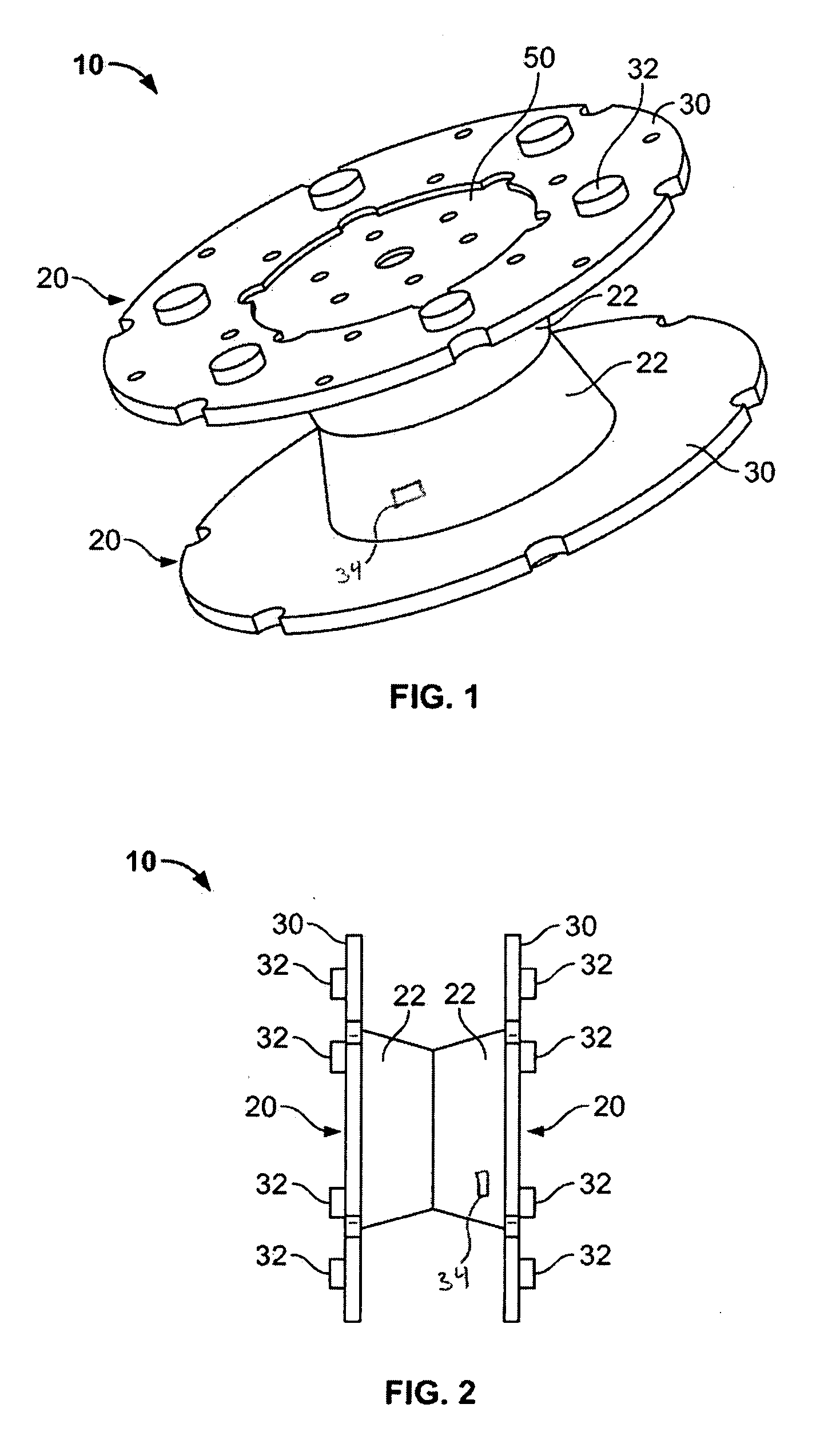
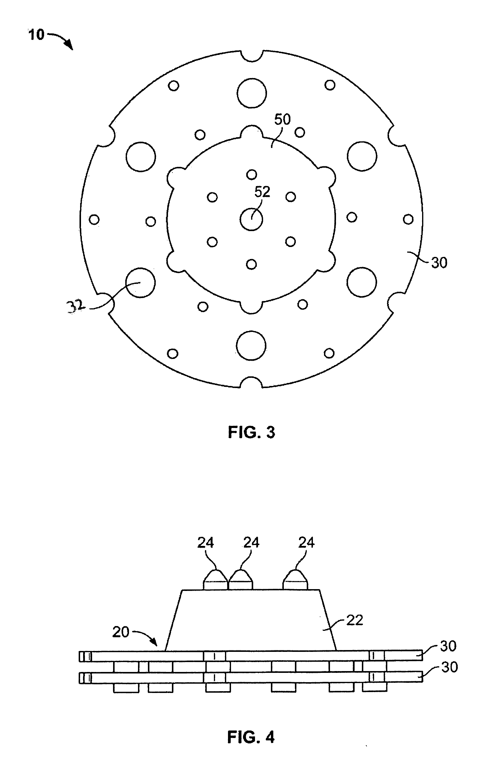
[0032]the present invention is illustrated in FIGS. 1-5. In general, modular cable dunnage system 10 is a large, molded, two-part assembly that is symmetrical about the centerline. The assembly has first and second reel-hub halves 20. Each reel-hub half 20 of the assembly is formed from a single molded piece having a central, tapered, hub 22 that terminates with a flange 30. The tapered hub 22 allows easy insertion into a raw coil bundle for use by an end-user to unload the electrical wire and thus further allows the wire to be shipped with no reel attached. The terminal end of each hub contains a plurality of raised fittings or pins 24 and an equal plurality of apertures 26. Preferably, the fittings 24 and apertures 26 alternate in position to as to provide a self-aligning and interlocking structure when assembling the first and second reel-hub halves 20 together. The terminal end of each hub 22 preferably also has at least one bolt hole 36, by which the first and second reel-hub h...

fourth embodiment

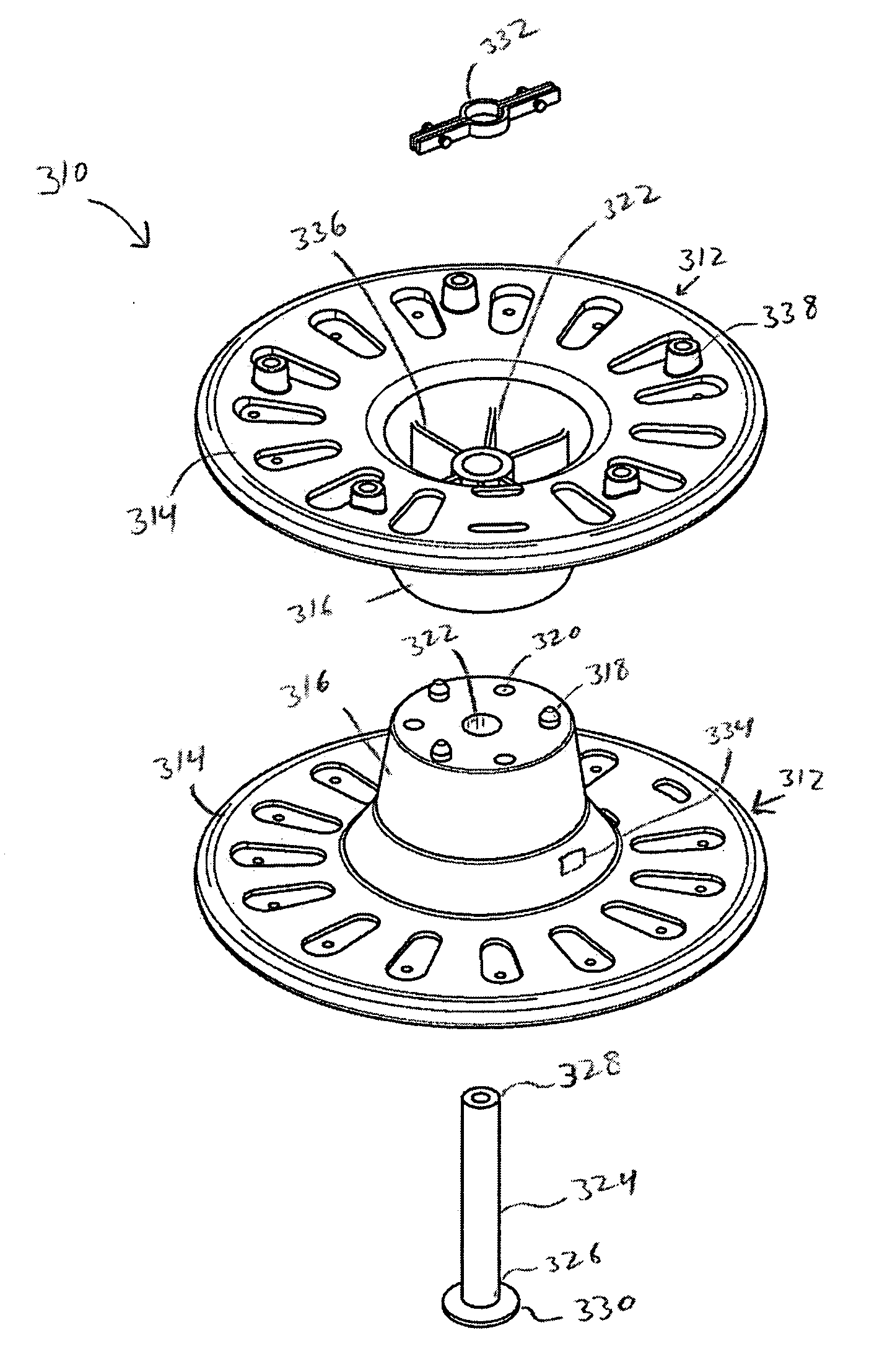
[0039]a modular cable dunnage system 310 of the present invention is illustrated in FIG. 15. Modular cable dunnage system 310 has two reel-hub halves 312. Each reel-hub half 312 has a flange portion 314 and a hub portion 316. The hub portion 316 of each reel-hub half 312 has a flange end and a terminal end, and is preferably tapered such that the diameter of the hub portion 316 is the greatest at the flange end, near the flange portion 314, and decreases towards the terminal end. A tapered hub portion allows easy insertion into a raw coil bundle for use by an end-user to unload the electrical wire and thus further allows the wire to be shipped with no reel attached. Preferably, each reel-hub half 312 has support gussets 334 extending radially from the central aperture 322, to provide increased structural integrity. At least one of the reel-hub halves 312 can be formed with a slot 334 in the hub portion 316, that insertably receives the tail end of an electrical cable or wire into th...


PUM

PropertyMeasurementUnit
angleaaaaaaaaaa
angleaaaaaaaaaa
nesting angleaaaaaaaaaa

Abstract

A modular dunnage system for the transportation, storage and dispensation of electrical wire and cable. Embodiments of modular cable dunnage system generally comprise at least two flange portions and at least two hub portions. In some embodiments, the system has two reel-hub halves that each comprise a flange portion and a hub portion. In other embodiments, the system has two flange portions and two or more hub portions that interlock and connect with the flange portions.

Description

RELATED APPLICATIONS[0001]This application is a continuation-in-part of U.S. patent application Ser. No. 11 / 279,424, filed on Apr. 12, 2006, currently pending, which claims the benefit of U.S. Provisional Patent Application Ser. No. 60 / 671,845, filed Apr. 15, 2005, now abandoned, the disclosures of which are hereby incorporated by reference in their entirety.BACKGROUND[0002]The present invention finds use in the field of electrical wire and cable. More particularly, the present invention relates to systems for packaging, handling, shipping and storage of electrical wire and cable.[0003]The packaging, transportation, handling and storage of bulk quantities of thick filamentous materials, such as cable, wire, and rope, have always presented special challenges to their respective manufacturers and end users. Long strands of filamentous materials must be handled in a particular fashion to facilitate use and distribution while, at the same time, protecting the product from damage. By the...

Claims


Application Information

Patent Timeline
Patent Type & Authority Applications(United States)
IPC IPC(8): B65H75/14B23P11/00
CPCB65H75/148B65H75/22B65H75/285Y10T29/49826B65H2701/512B65H2701/534H02G11/02B65H2701/34B65H75/2227B65H75/2263
Inventor AISTON, CHRISTOPHER J.HOELL, JOSEPH A.
Owner AISTON CHRISTOPHER J
Learn More