Electric drive unit

a technology of electric drive and drive shaft, which is applied in the direction of electronic commutators, motor/generator/converter stoppers, dynamo-electric converter control, etc., can solve the problem of even variation in the weight of trailing cables, and achieve the effect of minimizing the additional losses resulting from the position detection function

Active Publication Date: 2009-04-02
SIEMENS AG
View PDF7 Cites 5 Cited by
  • Summary
  • Abstract
  • Description
  • Claims
  • Application Information

AI Technical Summary

Benefits of technology

[0030]In an advantageous embodiment and development of the invention, the drive unit is designed in such a way that the current component resulting from the impressed alternating voltage at the stator end is compensated for in that location by a further alternating voltage being impressed. Additional losses resulting from the position detection function are thus minimized.

Problems solved by technology

Problems inherent these known solutions to the problem are:additional space / weight required for the energy transmission system: in the case of trailing cables, the weight of trailing cables moved is even variable.wear, friction, contamination.

Method used


Image

  • Electric drive unit
  • Electric drive unit
  • Electric drive unit

Examples


Embodiment Construction

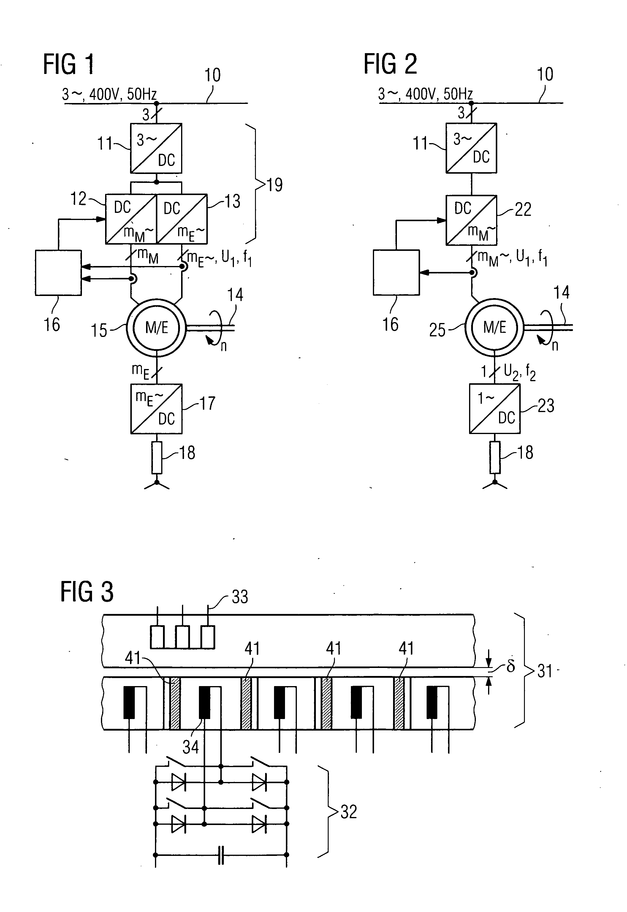
[0038]The main embodiments according to the invention will emerge from FIGS. 1 and 2. The further figures each show individual aspects for various embodiment possibilities.

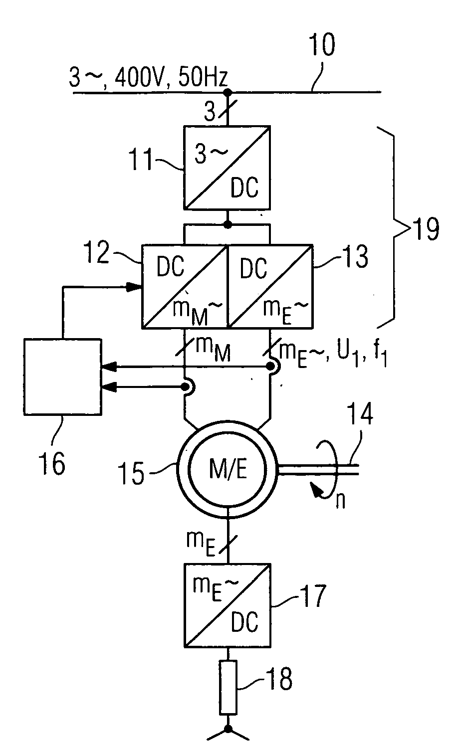
[0039]FIG. 1 shows a drive unit 15 connected to a three-phase network 10, said unit containing a system for energy transmission. FIG. 1 further shows a power converter 19, which consists specifically of a rectifier 11 and two inverters 12 and 13 connected to the direct voltage intermediate circuit. The first inverter 12 is responsible for the motor's drive function and the second inverter 13 for the energy transmission function. Both inverters 12, 13 act on corresponding stator windings in the drive unit 15, the stator windings being accommodated in a common active part. The drive unit 15 further has a drive shaft 14, which rotates at the speed n. There is furthermore an electrical load 18 shown symbolically as an ohm resistor. The electrical load 18 is supplied with power via the energy transmission system, the e...


PUM


Abstract

Electric drive units comprising a common active part having a stator and a rotor, which has windings and/or permanent magnets for a drive function and an energy transmission function, enable the rotor winding that is provided for energy transmission to be used to allow position detection at a low additional cost. For this purpose, a power converter in the rotor, which provides the output of electrical energy for the energy transmission function, impresses an alternating voltage into the rotor winding, said voltage being detected in the stator and allowing the rotor position to be determined.

Description

CROSS REFERENCE TO RELATED APPLICATIONS[0001]This application claims priority of German application No. 10 2007 046 513.2 DE filed Sep. 28, 2007, which is incorporated by reference herein in its entirety.FIELD OF INVENTION[0002]The invention relates to an electric drive unit. Such a drive unit is constructed in particular according to the principle of a synchronous motor, an asynchronous motor or a synchronous reluctance motor and can be used as a linear or rotary drive.BACKGROUND OF INVENTION[0003]Electric drive units consist of a stator and a rotor that is moved in relation to the stator. In such motors, electrical power on the rotor is sometimes required, for example:[0004]to control the drive power by having a separate supply for the rotor, such as, for example, exciter power in an electrically excited synchronous motor or dual fed asynchronous motor.[0005]as auxiliary energy for loading and unloading in transport tasks, clamping of work pieces or tools, for sensor systems to de...

Claims


Application Information

Patent Timeline
Patent Type & Authority Applications(United States)
IPC IPC(8): H02P6/18
CPCH02P9/007
Inventor WEIGEL, JAN
Owner SIEMENS AG
Why Eureka
Try Eureka