Liquid droplet measurement apparatus and liquid droplet measurement method
- Summary
- Abstract
- Description
- Claims
- Application Information
AI Technical Summary
Benefits of technology
Problems solved by technology
Method used
Image

Examples
first embodiment
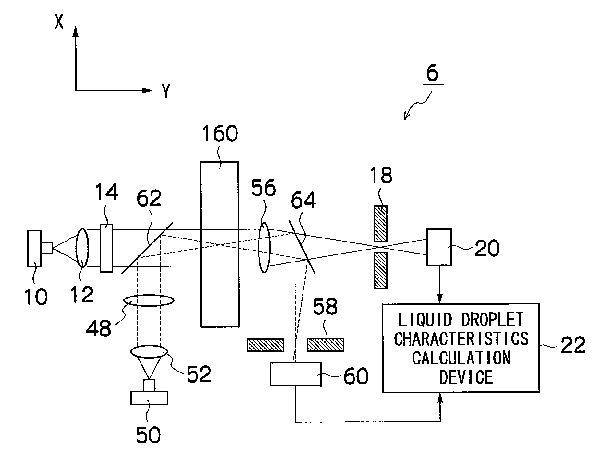
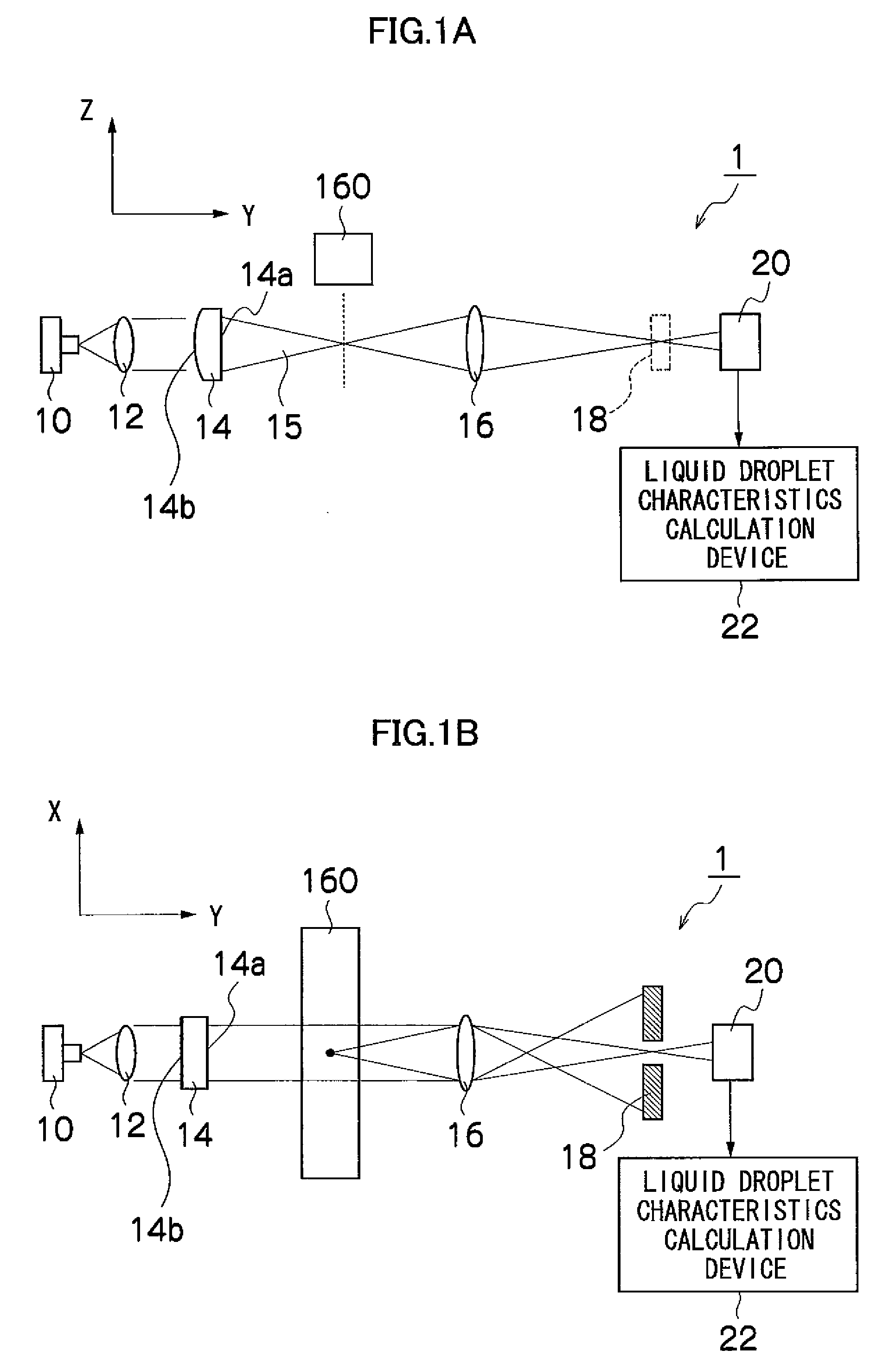
[0089]FIGS. 1A and 1B are schematic drawings of a liquid droplet measurement apparatus 1 according to a first embodiment; FIG. 1A is a front view and FIG. 1B is a lower side view. As illustrated in FIGS. 1A and 1B, the liquid droplet measurement apparatus 1 according to an embodiment of the present invention comprises a laser light source 10 (first laser light source), a first optical device, a first photoreceptor device and a liquid droplet characteristics calculation device 22, and the like.
[0090]The laser light source 10 may use, apart from the semiconductor laser light source (LD light source), a solid laser light source, a liquid laser light source, a gas laser light source, or the like, but in the present embodiment, a semiconductor laser light source (LD light source) is used. The reason for this is that it allows the apparatus to be made smaller in size, as well as reducing the related costs.
[0091]The laser light source 10 is disposed in such a manner that the direction hori...
second embodiment
[0131]Furthermore, a liquid droplet measurement apparatus 2 such as that illustrated in FIGS. 14A and 14B can also be conceived. In the liquid droplet measurement apparatus 2 according to the second embodiment, the first optical device comprises a collimating lens 12, a cylindrical lens 24, a cylindrical lens 26 and a spherical lens 16 provided in this order from the laser light source 10.
[0132]In the plane illustrated in FIG. 14A, the generatrix of the cylindrical lens (24, 26) is parallel to the plane of the drawing, and the refractive power of the cylindrical lens (24, 26) is zero. Consequently, in the plane illustrated in FIG. 14A, after the laser light incident from the laser light source 10 via the collimating lens 12 has exited from the cylindrical lens (24, 26), it proceeds while maintaining the width at the time of exiting from the collimating lens 12.
[0133]On the other hand, in the planar view illustrated in FIG. 14B, the flat side face 24a of the cylindrical lens 24 faces...
third embodiment
[0145]Furthermore, the liquid droplet measurement apparatus 3 illustrated in FIG. 15 can also be conceived. In the liquid droplet measurement apparatus 3 according to the third embodiment, the optical device comprises a collimating lens 12, a diffusion plate 28, a spherical lens 32, a spherical lens 34, a spherical lens 38, and a spherical lens 16, provided in this order from the laser light source 10.
[0146]By disposing the spherical lens 32 and the spherical lens 34 between the diffusion plate 28 and the ejection path of the liquid droplet in this way, the spherical lens 32 and the liquid droplet, and the diffusion plate 28 and the spherical lens 34, are respectively positioned in optically conjugated relationships.
[0147]The diffusion plate 28 diff-uses the laser light only in the direction perpendicular to the direction of ejection of the liquid droplet (X axis direction) and therefore the laser light is not diffused in the direction of ejection of the liquid droplet (Z axis direc...
PUM
 Abstract
Description
Claims
Application Information
 - Generate Ideas
- Intellectual Property
- Life Sciences
- Materials
- Tech Scout
- Unparalleled Data Quality
- Higher Quality Content
- 60% Fewer Hallucinations
Browse by: Latest US Patents, China's latest patents, Technical Efficacy Thesaurus, Application Domain, Technology Topic, Popular Technical Reports.
© 2025 PatSnap. All rights reserved.Legal|Privacy policy|Modern Slavery Act Transparency Statement|Sitemap|About US| Contact US: help@patsnap.com