Multilayer capacitor
a multi-layer capacitor and capacitor technology, applied in the direction of fixed capacitors, stacked capacitors, fixed capacitor details, etc., can solve the problems of capacitor manufacturer, power supply for a central processing unit (cpu) in a computer experiences voltage noise, localized heat spots,
- Summary
- Abstract
- Description
- Claims
- Application Information
AI Technical Summary
Benefits of technology
Problems solved by technology
Method used
Image

Examples
first embodiment
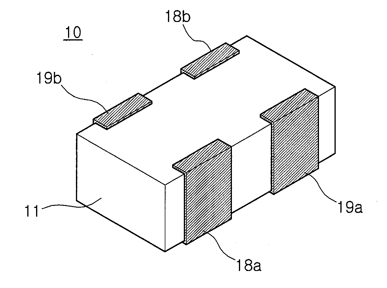
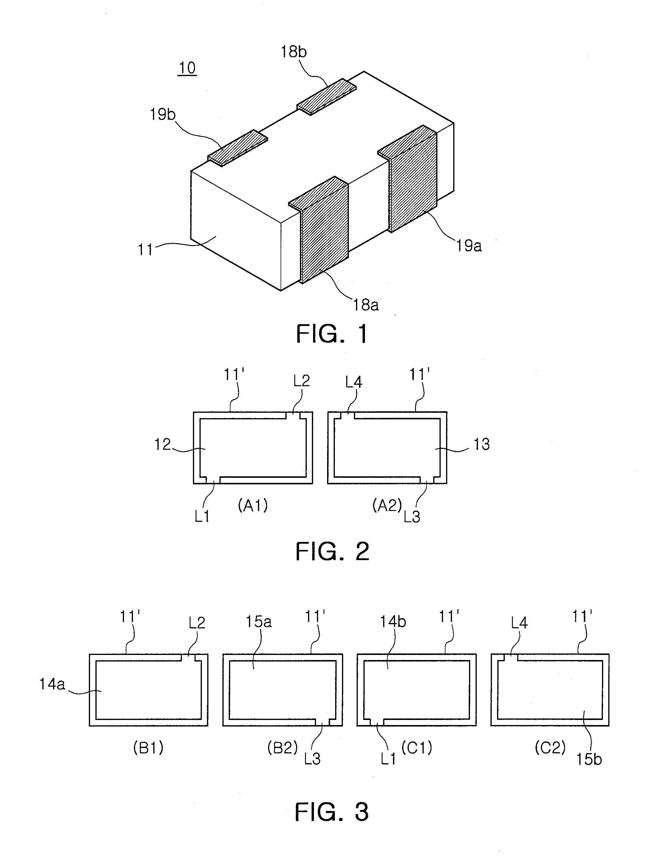
[0065]FIG. 1 illustrates a four-terminal multilayer capacitor according to the invention.
[0066]Referring to FIG. 1, the multilayer capacitor 10 of the present embodiment includes a capacitor body 11 having a plurality of dielectric layers 11′ laminated therein.
[0067]The multilayer capacitor 10 includes two first outer electrodes 18a and 18b and two second outer electrodes 19a and 19b formed on both opposing side surfaces to be electrically insulated from each other.
[0068]The first and second outer electrodes 18a and 18b; 19a and 19b may be arranged such that adjacent ones of the outer electrodes have opposite polarities to each other to reduce equivalent series inductance (ESL). In the present embodiment, the outer electrodes of different polarities are disposed at corresponding positions on the both opposing side surfaces. Accordingly, this allows for a reduction in ESL.
[0069]As shown in FIGS. 2 and 3, the multilayer capacitor 10 may include first and second inner connecting conduc...
third embodiment
[0109]FIG. 8 is a perspective illustrating a six terminal multilayer capacitor according to the invention.
[0110]Referring to FIG. 8, the multilayer capacitor 60 includes a capacitor body 61 having a plurality of dielectric layers 61′ laminated therein.
[0111]The multilayer capacitor 60 includes three first electrodes 68a, 68b and 68c and three second outer electrodes 69a, 69b, and 69c formed on both opposing side surfaces to be electrically insulated from each other. As in the present embodiment, the first and second outer electrodes may be arranged such that adjacent ones of the outer electrodes have different polarities.
[0112]According to a first aspect of the invention, the multilayer capacitor 60 is structured to adjust ESR using an inner connecting conductor.
[0113]In the present embodiment, as shown in FIG. 9, the multilayer capacitor 60 includes first and second inner connecting conductors 62 and 63 formed on the plurality of dielectric layers 61′, respectively. The first inner...
fourth embodiment
[0139]FIG. 13 is a perspective view illustrating a six terminal multilayer capacitor according to the invention.
[0140]Referring to FIG. 13, the multilayer capacitor 90 of the present embodiment includes a capacitor body 91 where a plurality of dielectric layers 91 are laminated.
[0141]The capacitor body 91 is formed of a rectangular parallelepiped structure having opposing first and second main surfaces and four side surfaces interposed therebetween. The multilayer capacitor 90 includes respective three first and second outer electrodes 98a, 98b, and 98c; 99a, 99b, and 99c arranged to have different polarities alternating along the four side surfaces.
[0142]Moreover, as shown in FIG. 13, two first and second outer electrodes are formed on both opposing side surfaces (length direction) of the body 91, respectively, and first and second outer electrodes are formed on the other opposing side surfaces (width direction), respectively.
[0143]As shown in FIG. 14, the multilayer capacitor 90 m...
PUM
 Abstract
Description
Claims
Application Information
 - R&D
- Intellectual Property
- Life Sciences
- Materials
- Tech Scout
- Unparalleled Data Quality
- Higher Quality Content
- 60% Fewer Hallucinations
Browse by: Latest US Patents, China's latest patents, Technical Efficacy Thesaurus, Application Domain, Technology Topic, Popular Technical Reports.
© 2025 PatSnap. All rights reserved.Legal|Privacy policy|Modern Slavery Act Transparency Statement|Sitemap|About US| Contact US: help@patsnap.com