
Cooling unit and display apparatus having the same

a display device and cooling unit technology, applied in the direction of ventilation systems, heating types, electrical apparatus casings/cabinets/drawers, etc., can solve the problems of lowering thermal reliability, affecting other elements with relatively high heating values, and difficult to improve cooling efficiency of display devices, etc., to achieve the effect of improving cooling efficiency and thermal reliability

Active Publication Date: 2009-04-02
SAMSUNG ELECTRONICS CO LTD
View PDF21 Cites 89 Cited by
  • Summary
  • Abstract
  • Description
  • Claims
  • Application Information

AI Technical Summary

Benefits of technology

[0009]The present general inventive concept provides a cooling unit which can effectively provide a cooling path to enhance cooling efficiency and thermal reliability, and a display apparatus having the same.
[0010]The present general inventive concept also provides a cooling unit which can independently cool an element having a relatively high heating value to minimize a thermal influence on other elements, and a display apparatus having the same.
[0011]The present general inventive concept also provides a cooling unit which can provide a cooling path so that air flowing in the cooling path and air flowing out of the cooling path may not be mixed with each other, and a display apparatus having the same.

Problems solved by technology

However, if a distance or a space between the display apparatus and the protection cover or the installation surface is too narrow, improving cooling efficiency of the display apparatus is difficult, thereby lowering thermal reliability thereof.
Thus, an element having a relatively high heating value may affect other elements.

Method used


Image

  • Cooling unit and display apparatus having the same
  • Cooling unit and display apparatus having the same
  • Cooling unit and display apparatus having the same

Examples


Embodiment Construction

[0044]Reference will now be made in detail to embodiments of the present general inventive concept, examples of which are illustrated in the accompanying drawings, wherein like reference numerals refer to like elements throughout. The exemplary embodiments are described below so as to explain the present general inventive concept by referring to the figures.

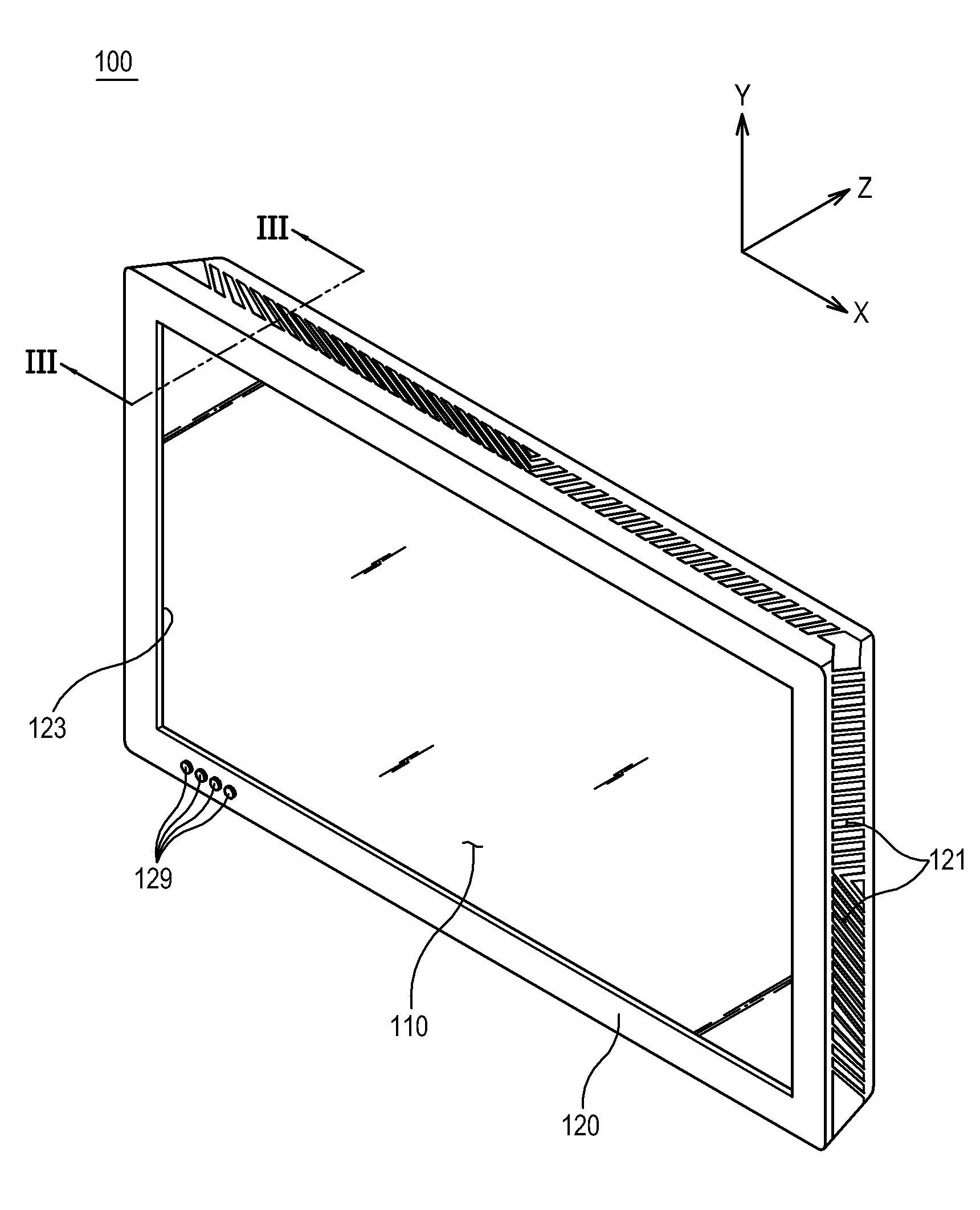
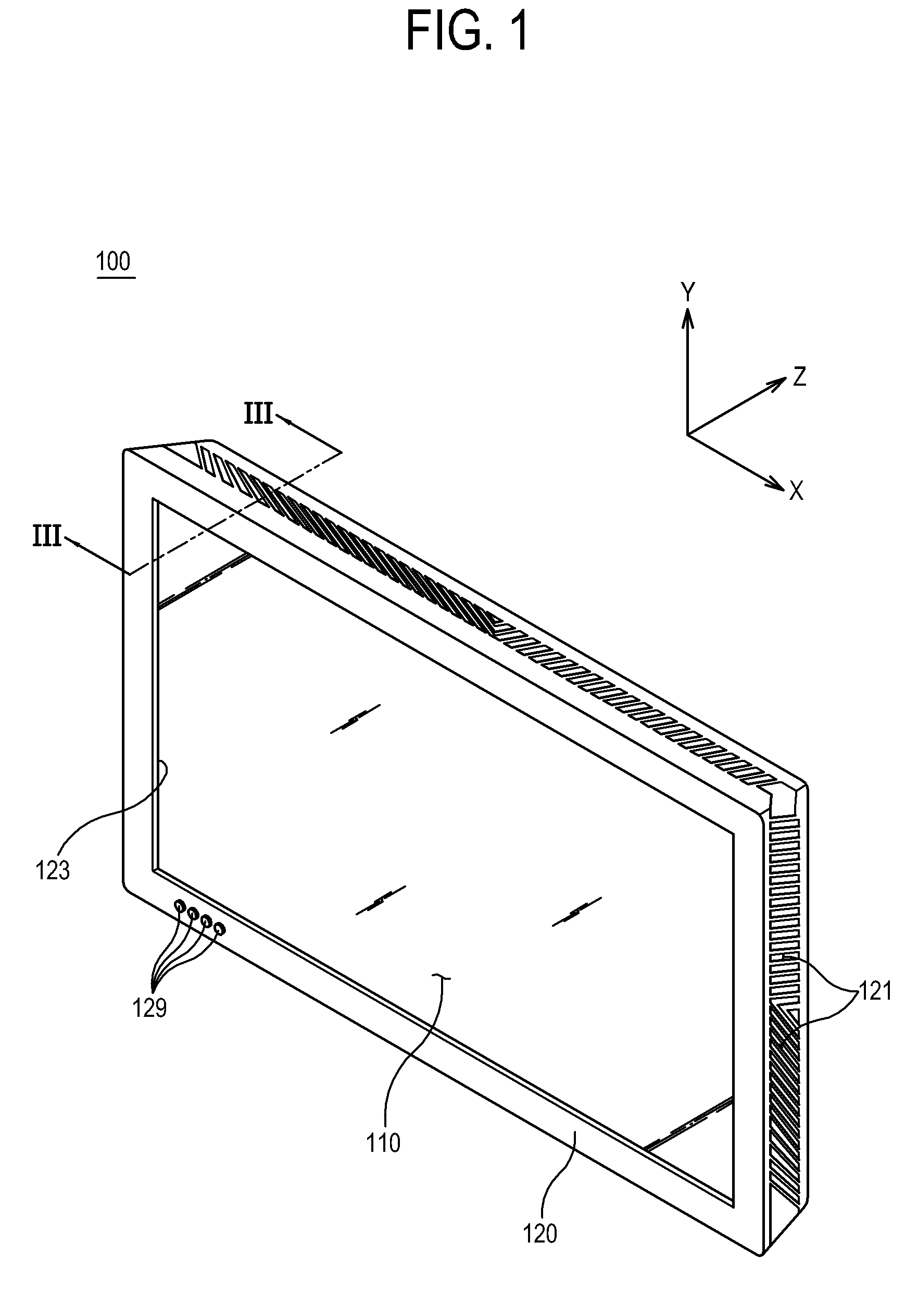
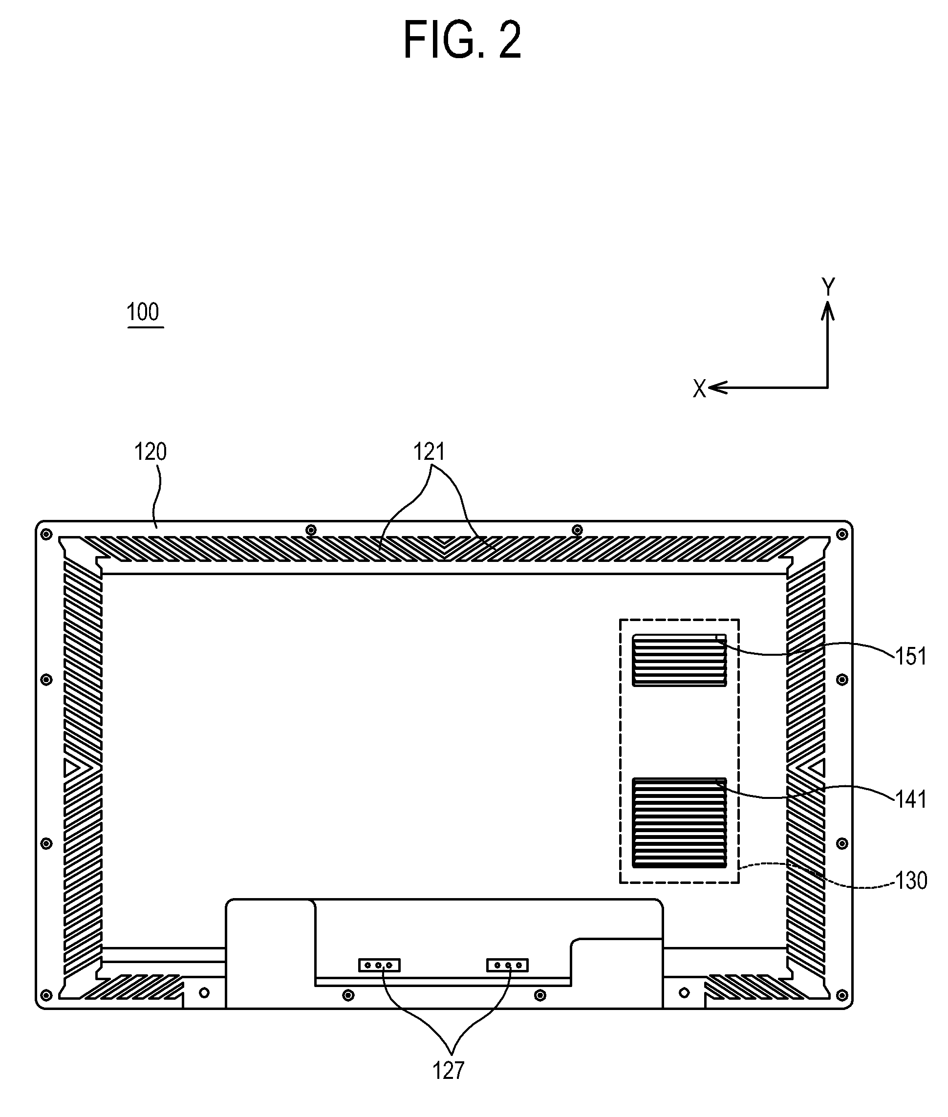
[0045]Referring to FIGS. 1 through 7, a display apparatus 100 according to an exemplary embodiment of the present general inventive concept includes a display panel 110; a casing 120; and a cooling unit 130.

[0046]The display apparatus 100 further includes a heat generating unit 125 which is coupled with a rear portion of the display panel 110 and performs various functions such as driving the display panel 110 or providing network information.

[0047]The display apparatus 100 may be arranged in a landscape direction, as illustrated in FIG. 1, or may be arranged in a portrait direction where necessary. Hereinafter, it is assumed tha...


PUM


Abstract

A cooling unit to cool the display apparatus including a heat generating unit to generate heat and a casing to accommodate the heat generating unit, the cooling unit includes a cooling fan to generate air flow; a duct which is coupled with the casing and forms a cooling path to connect the cooling fan and the heat generating unit; an inlet portion which is provided to one side of the casing to communicate with the duct; an inlet grill which is provided in the inlet portion to guide air to be inhaled in a direction inclined to a rear surface of the casing; an outlet portion which is provided to an other side of the casing to communicate with the duct, being spaced from the inlet portion; and an outlet grill which is provided in the outlet portion to guide air to be exhaled in a direction inclined to a rear surface of the casing, wherein the exhaled direction provided by the outlet grill is different from the air-inhaling direction provided by the inlet grill. With this configuration, the cooling path is effectively provided to enhance cooling efficiency and thermal reliability.

Description

CROSS-REFERENCE TO RELATED APPLICATIONS[0001]This application claims priority under 35 U.S.C. §119(a) from Korean Patent Application No. 10-2007-0097396, filed on Sep. 27, 2007 in the Korean Intellectual Property Office, the disclosure of which is incorporated herein in its entirety by reference.BACKGROUND OF THE INVENTION[0002]1. Field of the Invention[0003]The present general inventive concept relates to a cooling unit which has improved cooling efficiency, and a display having the same.[0004]2. Description of the Related Art[0005]In general, a display apparatus such as a television, a monitor for a computer, or the like includes a display panel, a heat generating unit such as a printed circuit board which generates heat while driving the display panel, and a casing which forms an outside appearance.[0006]Recently, a digital information display (DID) has been actively developed meeting consumer's demand. The DID publicly provides various contents including characters and moving pi...

Claims


Application Information

Patent Timeline
Patent Type & Authority Applications(United States)
IPC IPC(8): H05K7/20F24F7/007F28F7/00
CPCG02F1/133385Y10S345/905H05K7/2099H05K7/20972H04N5/64
Inventor KANG, JOONCHO, JIN-HYUN
Owner SAMSUNG ELECTRONICS CO LTD
Learn More