Circuit device

Active Publication Date: 2009-04-02
SEMICON COMPONENTS IND LLC
View PDF28 Cites 42 Cited by
  • Summary
  • Abstract
  • Description
  • Claims
  • Application Information

AI Technical Summary

Benefits of technology

[0010]The present invention has been made in view of the problems described above. A main object of the present invention is to provide a cir

Problems solved by technology

As a result, the microcomputer heated by the

Method used


Image

  • Circuit device
  • Circuit device
  • Circuit device

Examples


Embodiment Construction

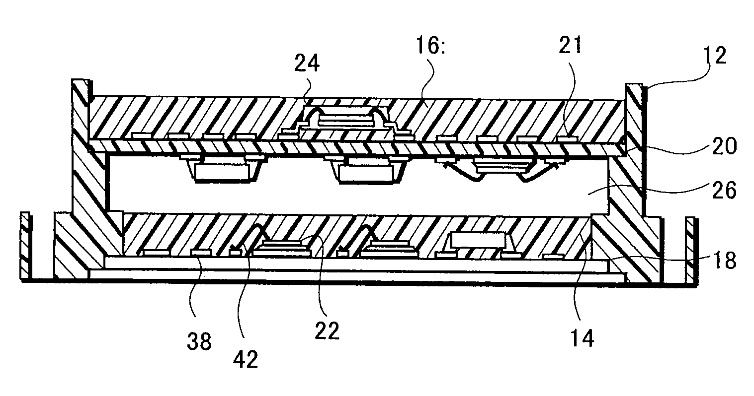
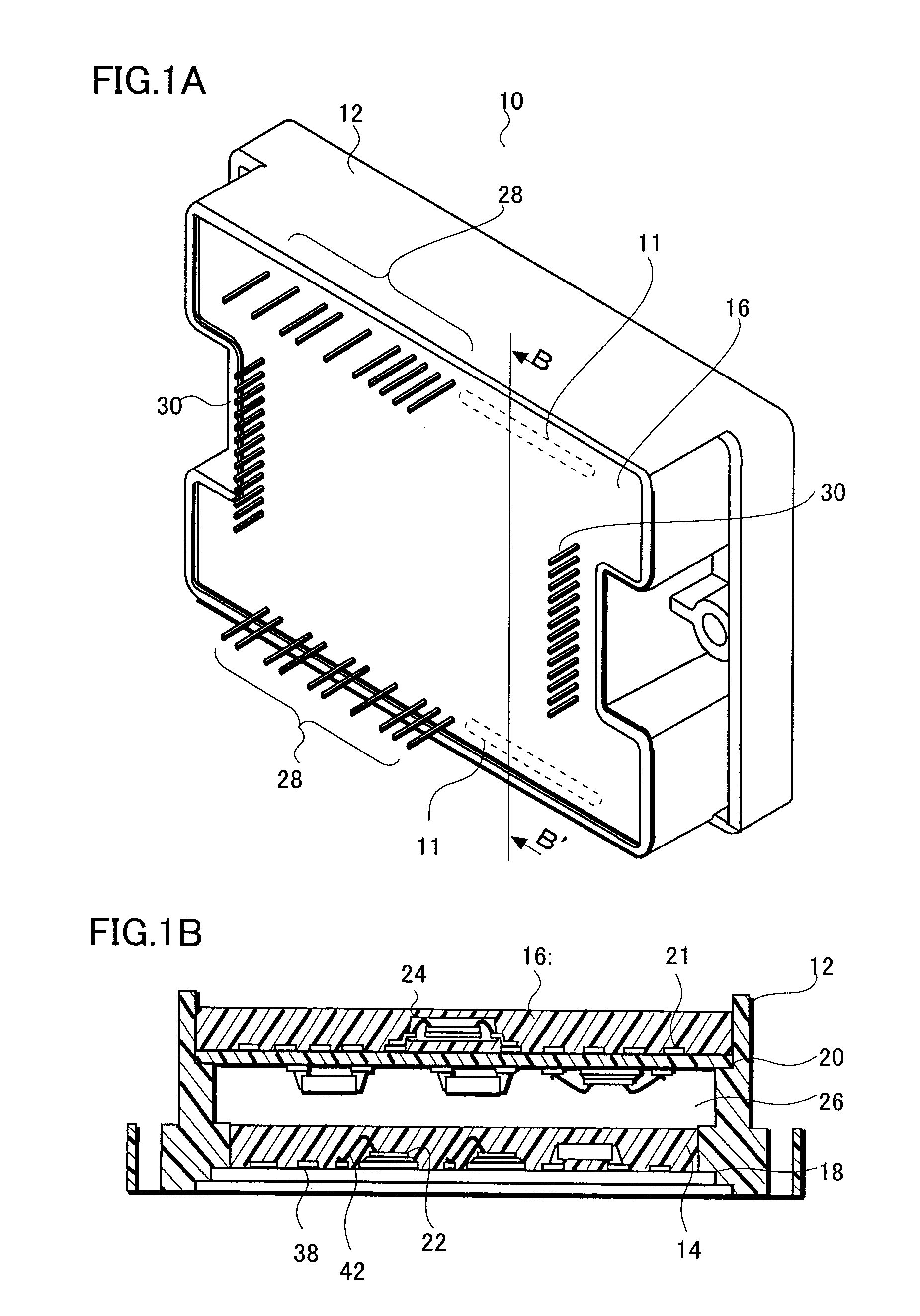
[0020]As an example of the circuit device, the configuration of a hybrid integrated circuit device 10 is described with reference to FIGS. 1A and 1B. FIG. 1A is a perspective view of the hybrid integrated circuit device 10, and FIG. 1B is a cross sectional view of FIG. 1A taken along a B-B′ line.

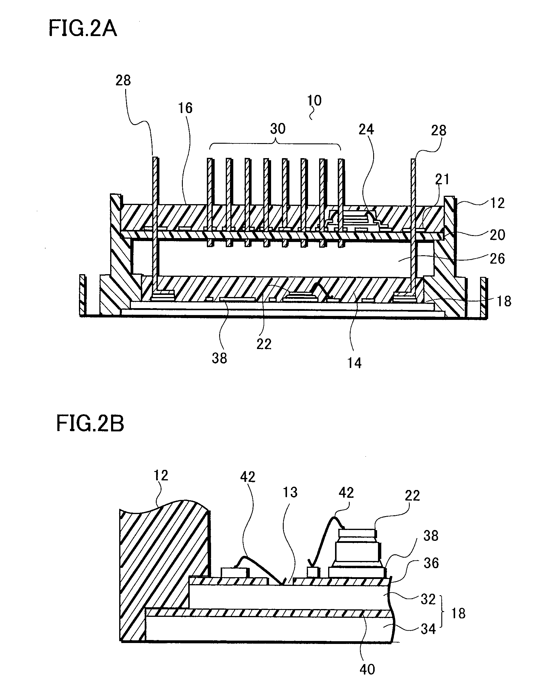
[0021]As shown in FIG. 1A and FIG. 1B, in the hybrid integrated circuit device 10, a first circuit board 18 is overlaid with a second circuit board 20 and both circuit boards are fitted into a case member 12. A first circuit element 22 (a power transistor, for example) is arranged on the upper surface of the first circuit board 18, and a second circuit element 24 (a microcomputer, for example) is arranged on the upper surface of the second circuit board 20. In addition, inside the case member 12, a hollow portion 26 which is not filled with a sealing resin is provided.

[0022]The case member 12 is formed by injection molding a thermosetting resin, such as an epoxy resin, or a thermoplastic res...


PUM


Abstract

Provided is a circuit device capable of increasing the packaging density and preventing the thermal interference between circuit elements to be incorporated. In a hybrid integrated circuit device, a first circuit board and a second circuit board are fitted into a case member in a way that the first circuit board is overlaid with the second circuit board. A first circuit element is arranged on the upper surface of the first circuit board and a second circuit element is arranged on the upper surface of the second circuit board. Furthermore, inside the case member, provided is a hollow portion that is not filled with a sealing resin. Such a configuration prevents the second circuit element, which is a microcomputer, from operating unstably due to a heat generated in the first circuit element, which is a power transistor, for example.

Description

[0001]This application claims priority from Japanese Patent Application Number JP 2007-250483, filed on Sep. 27, 2007, the content of which is incorporated herein by reference in its entirety.BACKGROUND OF THE INVENTION[0002]1. Field of the Invention[0003]The present invention relates to a circuit device, and particularly to a circuit device in which a hybrid integrated circuit formed on an upper surface of a circuit board is sealed with a case member.[0004]2. Description of the Related Art[0005]The configuration of a hybrid integrated circuit device 150 employing a case member 111 is described with reference to FIG. 7. The hybrid integrated circuit device 150 includes: a substrate 101 made of a metal, such as aluminum; an insulating layer 102 formed so as to cover the upper surface of the substrate 101; a conductive pattern 103 formed on the upper surface of the insulating layer 102; and a circuit element 110 such as a transistor electrically connected to the conductive pattern 103...

Claims


Application Information

Patent Timeline
IPC IPC(8): H05K7/00
CPCH05K1/144H01L2224/4903H05K3/3447H05K5/065H05K2201/042H05K2201/10318H05K3/284H01L2224/48091H01L2924/13055H01L2924/3025H01L2924/1305H01L2224/32225H01L2224/48227H01L2224/73265H01L2924/00H01L2924/00012H01L2924/00014H01L24/73H01L2924/14
Inventor SAKAMOTO, HIDEYUKISAITO, HIDEFUMIKOIKE, YASUHIROTSUKIZAWA, MASAO
Owner SEMICON COMPONENTS IND LLC
Why Eureka
Try Eureka