Planar lighting device

a lighting device and planar technology, applied in the direction of lighting and heating equipment, instruments, mechanical equipment, etc., can solve the problems of reducing the distance that light is capable of traveling, limiting the extent to which the dimensions of the planar lighting device can be increased, and reducing the density of scattering particles near the light entrance plane. , to achieve the effect of reducing light use efficiency, limiting the occurrence of brightness unevenness, and reducing the density of scattering particles near the light entrance plan

Active Publication Date: 2009-04-02
FUJIFILM CORP
View PDF10 Cites 23 Cited by
  • Summary
  • Abstract
  • Description
  • Claims
  • Application Information

AI Technical Summary

Benefits of technology

[0014]To achieve increased dimensions with a planar lighting device using any of the light guide plates disclosed in the above prior art literature, light needs to travel a longer distance from the light source, which in turn requires the light guide plate itself to be made thicker. Thus, the planar lighting device remain to have an unsolved problem of achieving reduction in thickness and weight.
[0018]Also proposed is a method whereby the light guide plate is provided with a reflection member near its light entrance planes to cause a multiple reflection of light such that the light leaking from the light entrance planes reenters the light guide plate, as will be described. This method, however, requires complicated means and therefore not only adds to the weight of a light guide plate when the light guide plate or its light exit plane is adapted to have large dimensions but increases manufacturing costs (JP 2004-171948 A, JP2005-108676 A, and JP 2005-302322 A). Further, light from the light sources is perceived as uneven brightness near the light entrance planes.
[0020]Then, the density of the scattering particles near the light entrance planes decrease even though the light use efficiency may be maintained. Accordingly, the extent to which light is scattered decreases, which tends to cause uneven brightness near the light entrance planes.
[0021]Thus, an object of the invention is to provide a planar lighting device solving the problems associated with the prior art described above and limiting the occurrence of brightness unevenness near the light entrance planes to provide improved illumination even when the light guide plate has a large light exit plane.

Problems solved by technology

Thus, the planar lighting device remain to have an unsolved problem of achieving reduction in thickness and weight.
Further, the shape having a tendency to decrease in thickness with the increasing distance from a position at which light from the light source is admitted or the flat plate shape as disclosed in the prior art literature mentioned above also pose a problem that a limited distance that light is capable of traveling limits the extent to which the dimensions of the planar lighting device can be increased.
While use of a light source having large light emission faces and hence providing more light to the light guide plate would enable emission of light with an increased brightness or an increased illuminance through the light exit plane, that approach is accompanied by a problem that there is a limit to the dimensions of the light emission face of the light source that can be used depending on the configuration of the light guide plate.
Besides, use of a larger light source or a light source providing a greater amount of light would increase the manufacturing costs of the device and power consumption thereof.

Method used


Image

  • Planar lighting device
  • Planar lighting device
  • Planar lighting device

Examples


first embodiment

[0048]the invention will be described first.

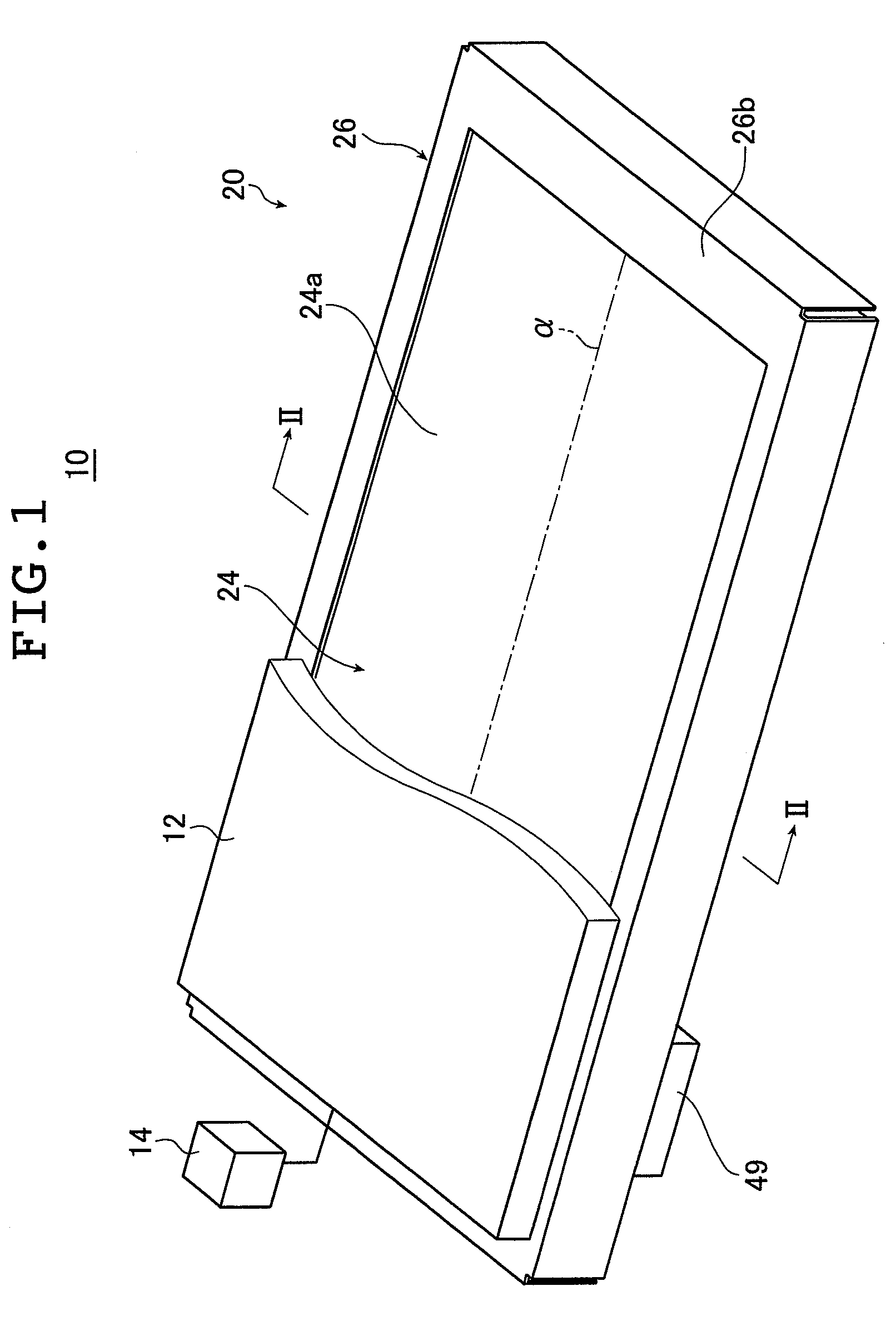
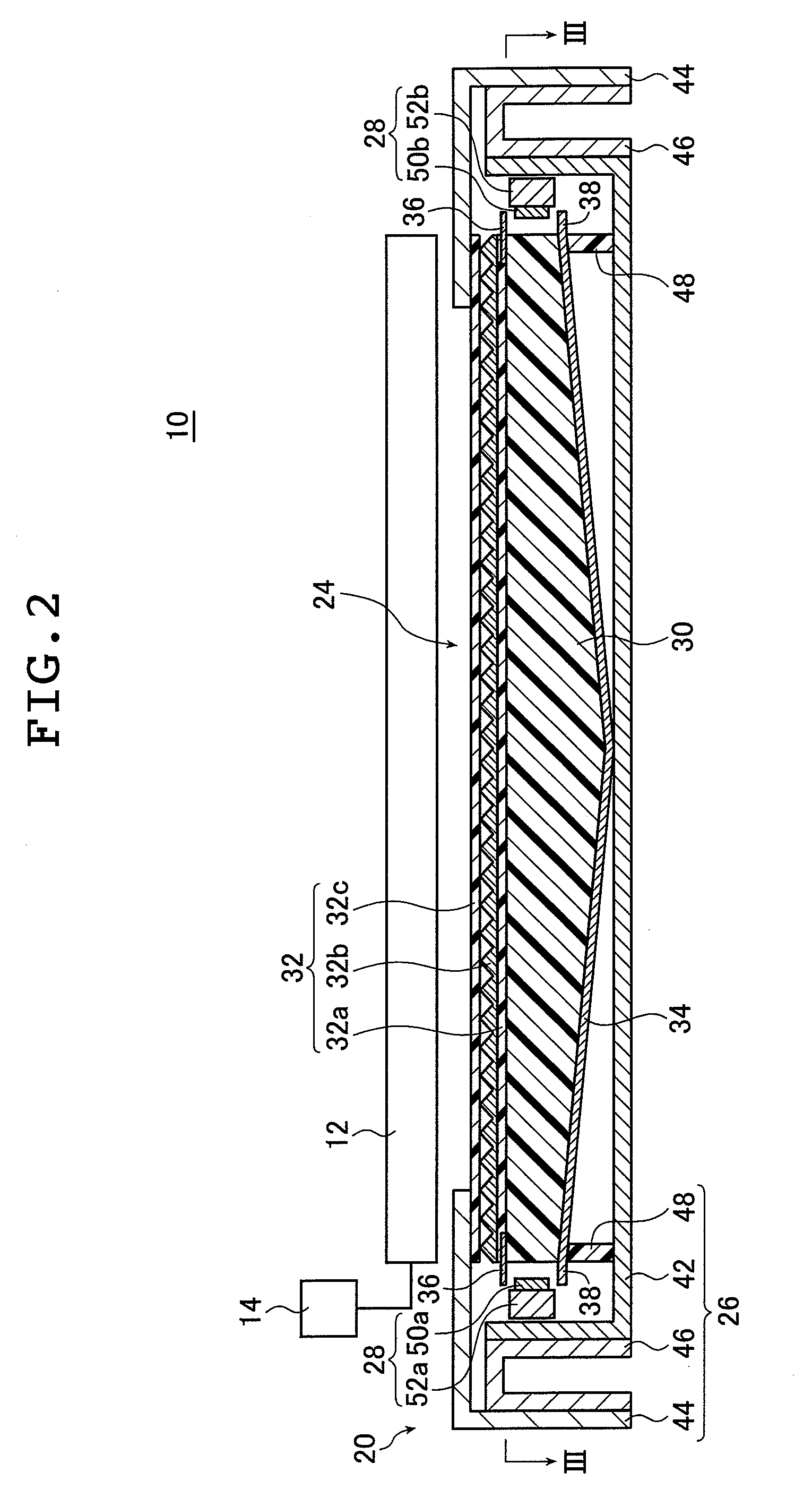
[0049]FIG. 1 is a schematic perspective view illustrating a liquid crystal display device provided with the planar lighting device of the invention; FIG. 2 is a cross sectional view of the liquid crystal display device illustrated in FIG. 1 taken along line II-II.

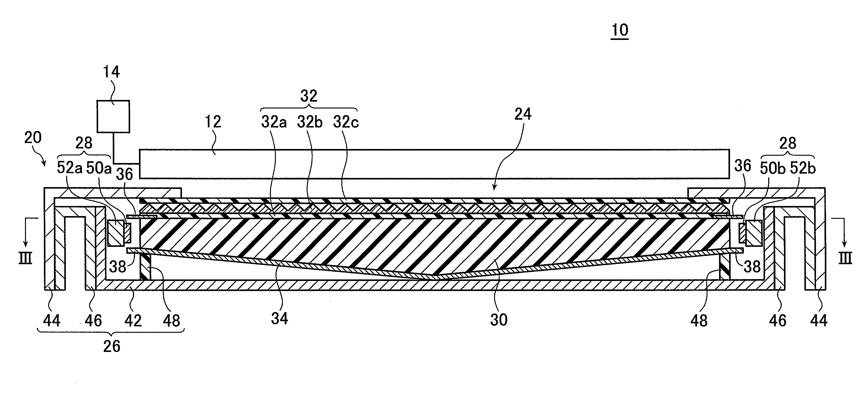
[0050]FIG. 3A is a view of the planar lighting device (also referred to as “backlight unit” below) illustrated in FIG. 2 taken along line III-III; FIG. 3B is a cross sectional view of FIG. 3A taken along line B-B.

[0051]A liquid crystal display device 10 comprises a backlight unit 20, a liquid crystal display panel 12 disposed on the side of the backlight unit closer to the light exit plane, and a drive unit 14 for driving the liquid crystal display panel 12. In FIG. 1, part of the liquid crystal display panel 12 is not shown to better illustrate the configuration of the planar lighting device.

[0052]In the liquid crystal display panel 12, electric field is partially applied to liqu...

second embodiment

[0160]As described above, the planar lighting device has the auxiliary light sources disposed respectively opposite the first auxiliary light entrance plane 30h and the second auxiliary light entrance plane 30i. With light thus admitted also through the lateral sides of the light guide plate 30, the planar lighting device is capable of emitting an increased amount of light with an increased brightness through the light exit plane 30a. Accordingly, a large amount of illumination light can be emitted through the light exit plane, which enables an enlarged light exit plane to be achieved, securing a larger display area for liquid crystal display devices.

[0161]The planar lighting device 20 is basically configured as described above.

[0162]In the planar lighting device 20, light emitted by the main light sources 28 provided on both sides of the light guide plate 30 strikes the light entrance planes, i.e., the first light entrance plane 30d and the second light entrance plane 30e, of the ...


PUM


Abstract

The planar lighting device includes, in addition to light sources, a light exit plane, a pair of light entrance planes formed on a pair of sides of the light exit plane, and a rear plane composed of a pair of inclined planes formed on a side opposite from the light exit plane such that the light guide plate grows thicker with an increasing distance from the light entrance planes toward the center. The light guide plate contains light scattering particles satisfying Npi>Np, where Npi is the particle density in a region of space within a given range of the light guide plate and Np the density in the other region of space. The planar lighting device with minimized brightness unevenness liable to develop near the light entrance planes when the light exit plane has great dimensions.

Description

[0001]The entire contents of literature cited in this specification are incorporated herein by reference.BACKGROUND OF THE INVENTION[0002]The present invention relates to a planar lighting device used for indoor and outdoor illumination and comprising light sources and a light guide plate for admitting light emitted by the light sources and emitting the light through the light exit plane thereof or to a planar lighting device used as a backlight for illuminating the liquid crystal display panel of a liquid crystal display device or as a backlight used for advertising panels, advertising towers, advertising signs, and the like.[0003]Liquid crystal display devices use a backlight unit for illuminating the liquid crystal display panel from the rear side thereof. A backlight unit is configured using optical members comprising a light guide plate for diffusing light emitted by an illuminating light source to irradiate the liquid crystal display panel, a prism sheet, and a diffusion sheet...

Claims


Application Information

Patent Timeline
Patent Type & Authority Applications(United States)
IPC IPC(8): F21V8/00
CPCG02B6/0041G02B6/0046G02B6/0073G02B6/0068G02B6/0061
Inventor IWASAKI, OSAMUKATSUMOTO, RYUICHI
Owner FUJIFILM CORP
Why Eureka
Try Eureka