
Planar lighting device

a lighting device and planar technology, applied in the direction of lighting device details, lighting and heating apparatus, instruments, etc., can solve the problems of limited distance that light can travel, limit the extent to which the dimensions of the planar lighting device can be increased, and the conventional light guide plates used were incapable of locally adjusting the illuminance observed at the light exit plane. , to achieve the effect of reducing the unevenness of illuminance and free from unevenness in illuminan

Inactive Publication Date: 2009-04-02
FUJIFILM CORP
View PDF11 Cites 22 Cited by
  • Summary
  • Abstract
  • Description
  • Claims
  • Application Information

AI Technical Summary

Benefits of technology

[0025]According to the invention, the configuration as described above enables efficient use of light emitted from the light source and emission of light from the light exit plane free from unevenness in illuminance (brightness) or with reduced unevenness in illuminance (brightness), as well as area control whereby the amount of light at the light exit plane is adjusted locally on an area by area basis and line control whereby the illuminance at the light exit plane is adjusted along any line desired.

Problems solved by technology

Thus, an attempt to enlarge the display area of a planar lighting device is confronted with difficulties in reducing the thickness and the weight of the planar lighting device.
Further, a planar lighting device using a light guide plate having the shape that has a tendency to decrease in thickness with the increasing distance from a position at which light from the light source is admitted or the flat plate shape as disclosed in the prior art literature mentioned above also poses a problem that a limited distance that light is capable of traveling limits the extent to which the dimensions of the planar lighting device can be increased.
Further, conventional light guide plates generally used were incapable of locally adjusting the illuminance observed at the light exit plane for an area desired by adjusting the illuminances at the light exit plane in the two mutually perpendicular directions thereof (referred to as “area control” below) or of adjusting the illuminance observed at the light exit plane in a single direction perpendicular to the light entrance planes for a position (line) desired perpendicular to a direction of movement (referred to as “line control” below).

Method used


Image

  • Planar lighting device
  • Planar lighting device
  • Planar lighting device

Examples


Embodiment Construction

[0054]The planar lighting device of the invention will be described in detail below referring to an embodiment illustrated in the accompanying drawings. First, the basic configuration of the inventive planar lighting device will be described.

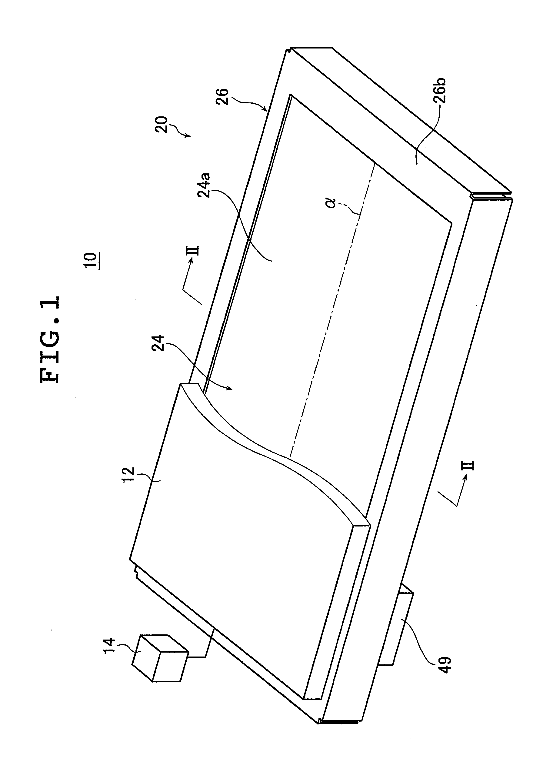
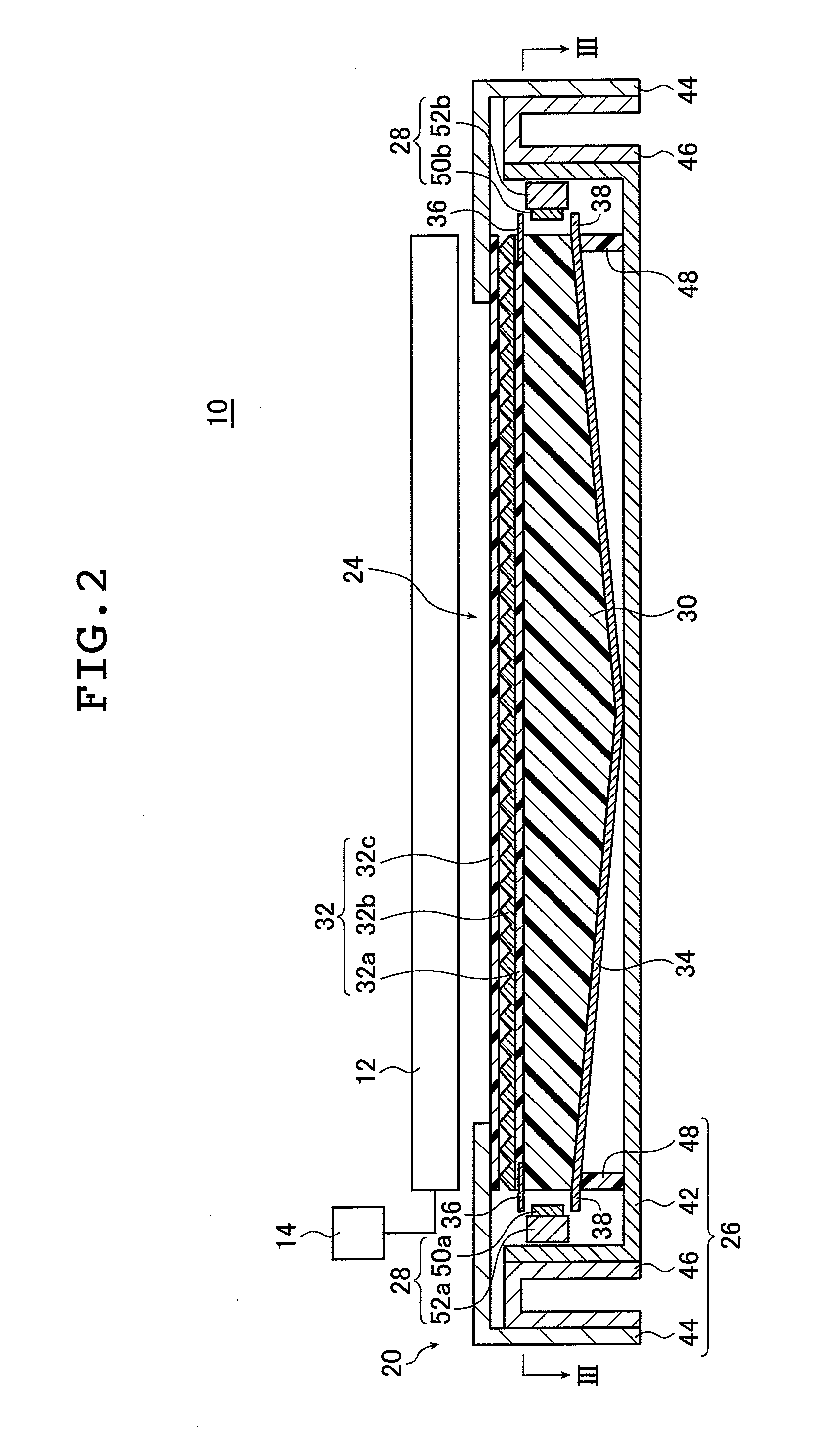
[0055]FIG. 1 is a schematic perspective view illustrating a liquid crystal display device provided with the planar lighting device of the invention; FIG. 2 is a cross sectional view of the liquid crystal display device illustrated in FIG. 1 taken along line II-II.

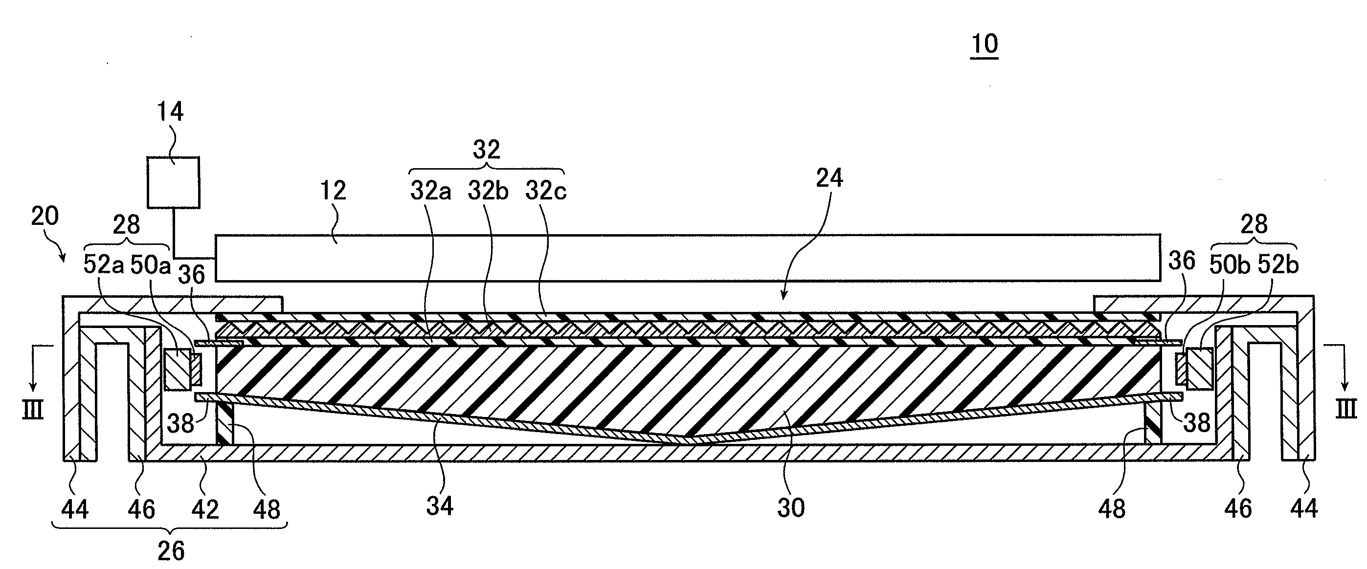
[0056]FIG. 3A is a view of the planar lighting device (also referred to as “backlight unit” below) illustrated in FIG. 2 taken along line III-III; FIG. 3B is a sectional view of FIG. 3A taken along line B-B.

[0057]A liquid crystal display device 10 comprises a backlight unit 20, a liquid crystal display panel 12 disposed on the side of the backlight unit closer to the light exit plane, and a drive unit 14 for driving the liquid crystal display panel 12. In FIG. 1, part of the liquid crys...


PUM


Abstract

The planar lighting device includes a light guide plate having the light exit plane, two pairs of light entrance planes formed at the four sides of the light exit plane, and rear planes formed opposite to the light exit plane and inclined such that the light guide plate grows thicker toward the center thereof, a pair of main light sources and a pair of auxiliary light sources disposed opposite their respective light entrance planes to emit light to the respective light entrance planes, and illuminance distribution control unit to adjust the amount of light emitted by the main and auxiliary light sources to form a designated local illuminance distribution for any position desired in the light exit plane. The planar lighting device performs area control and line control to adjust illuminance at a light exit plane for any area desired and along any line desired, respectively.

Description

[0001]The entire contents of literature cited in this specification are incorporated herein by reference.BACKGROUND OF THE INVENTION[0002]The present invention relates to a planar lighting device comprising light sources and a light guide plate for admitting light emitted by the light sources and emitting the light through the light exit plane thereof. The inventive planar lighting device is used for indoor and outdoor illumination or as a backlight to illuminate the liquid crystal display panel used in liquid crystal display devices or as a backlight used for advertising panels, advertising towers, advertising signs, and the like.[0003]Liquid crystal display devices use a backlight unit for radiating light from behind the liquid crystal display panel to illuminate the liquid crystal display panel. A backlight unit is configured using optical members comprising a light guide plate for diffusing light emitted by an illumination light source to irradiate the liquid crystal display pan...

Claims


Application Information

Patent Timeline
Patent Type & Authority Applications(United States)
IPC IPC(8): F21V7/04
CPCG02B6/0046G02B6/0085G02B6/0073G02B6/0068
Inventor IWASAKI, OSAMU
Owner FUJIFILM CORP
Features
  • Generate Ideas
  • Intellectual Property
  • Life Sciences
  • Materials
  • Tech Scout
  • Unparalleled Data Quality
  • Higher Quality Content
  • 60% Fewer Hallucinations
Learn More