
Index-matching gel for nanostructure optical fibers and mechanical splice assembly and connector using same

Inactive Publication Date: 2009-04-02
CORNING OPTICAL COMM LLC
View PDF39 Cites 42 Cited by
  • Summary
  • Abstract
  • Description
  • Claims
  • Application Information

AI Technical Summary

Benefits of technology

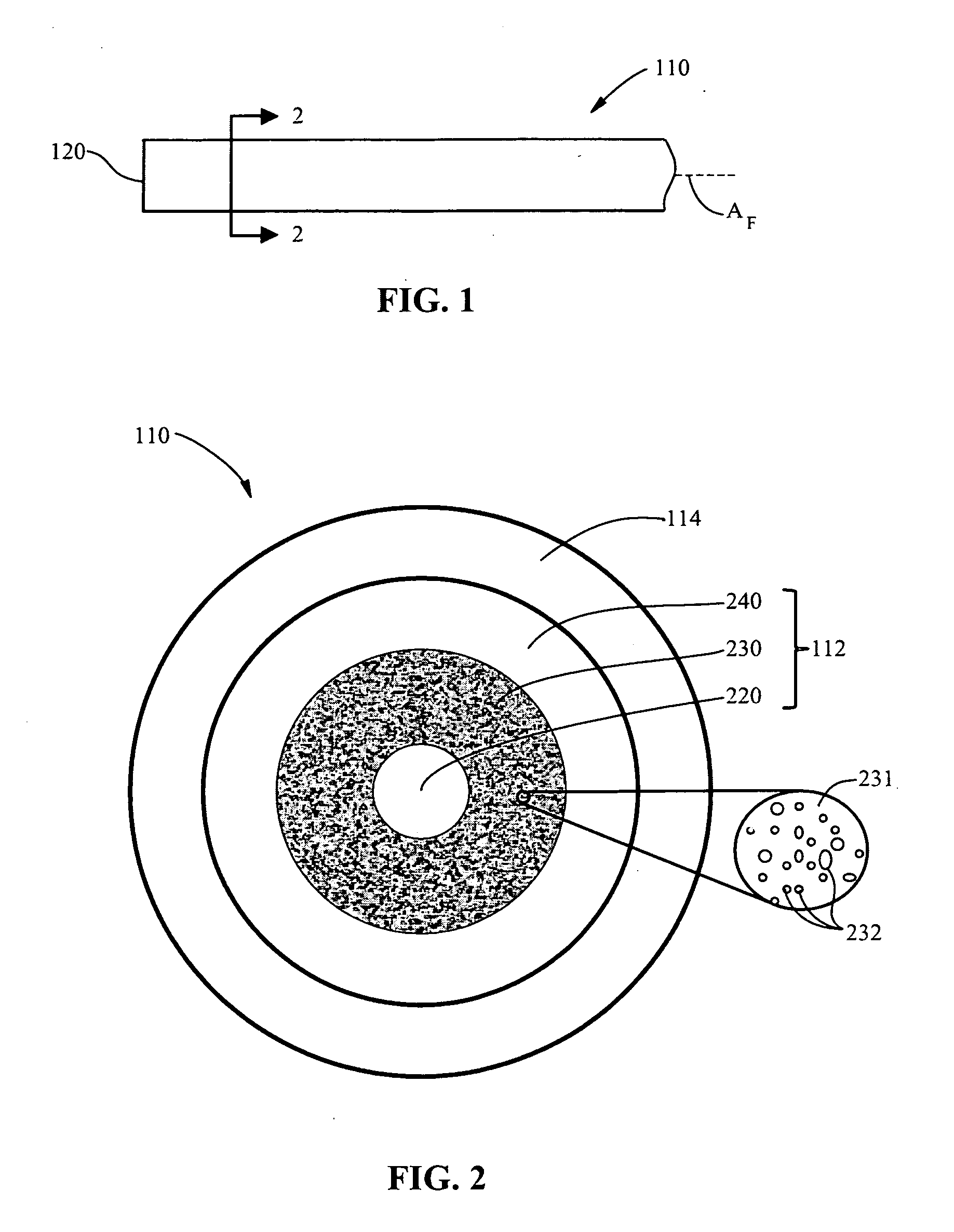
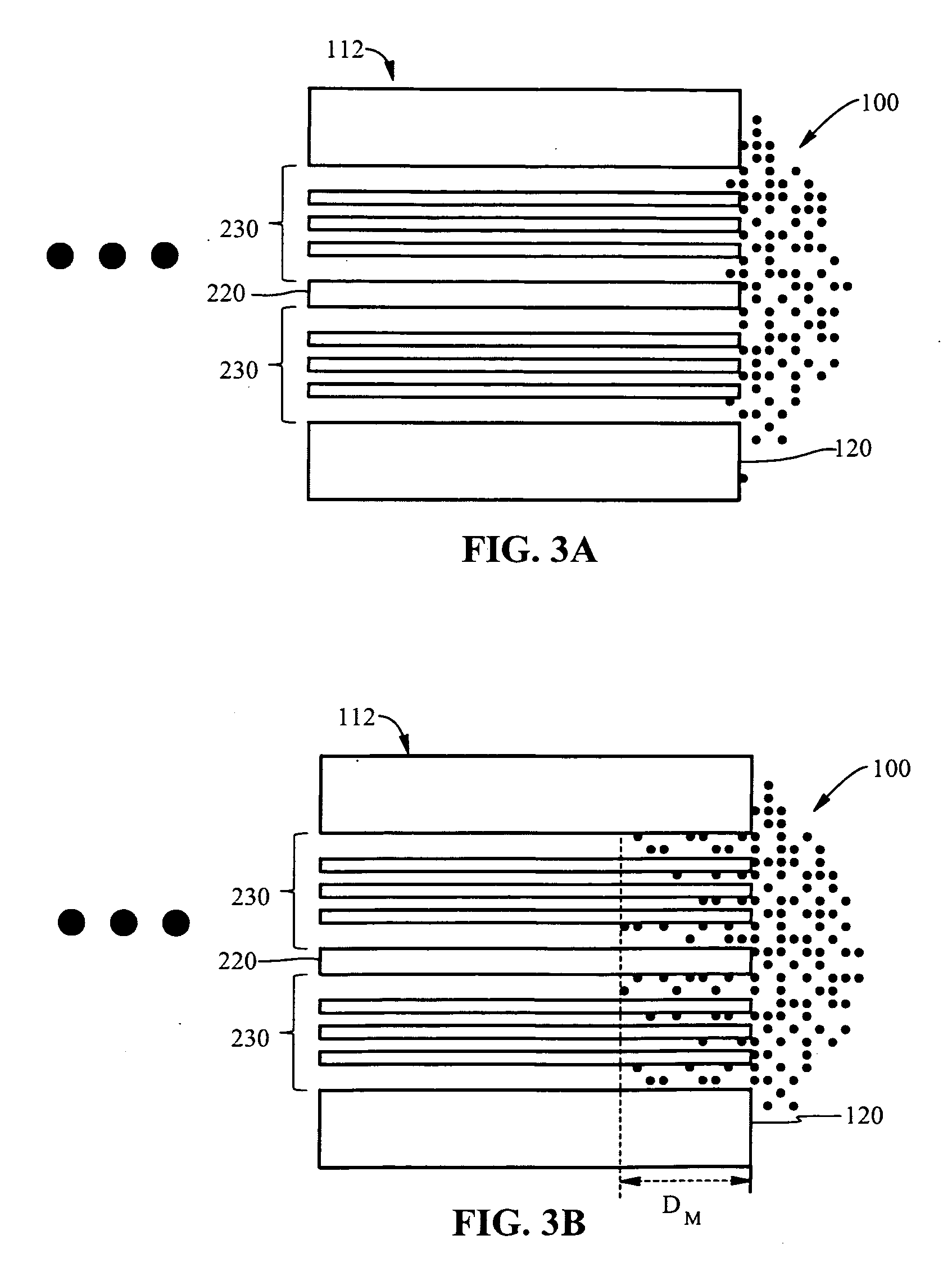
[0010]An aspect of the invention is a polymer based index-matching gel for use with nanostructure optical fibers. The gel has at least one polymer component having a viscosity η at 25° C. of 3 Pa-s≦η≦100 Pa-s, which prevents the index-matching gel from wicking into the voids and down the nanostructure optical fiber to a depth where the fiber performance and/or device performance is compromised. In one example, at leas...

Problems solved by technology

Connectors have traditionally been one of the main concerns in using fiber optic systems because they introduce loss and because different connector types were typically not compatible.

Method used


Image

  • Index-matching gel for nanostructure optical fibers and mechanical splice assembly and connector using same
  • Index-matching gel for nanostructure optical fibers and mechanical splice assembly and connector using same
  • Index-matching gel for nanostructure optical fibers and mechanical splice assembly and connector using same

Examples


example mechanical

Splice Assembly

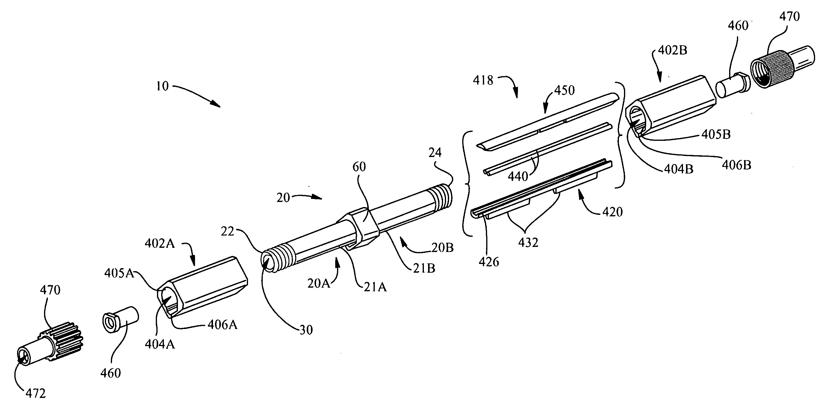
[0059]Aspects of the present invention include mechanical splice assemblies, and fiber optic connectors having such splice assemblies, that utilize the index-matching gel of the present invention. This makes the mechanical splice assemblies and connectors suitable for use with one or more nanostructure optical fibers, such as those described in the aforementioned Coming nanostructure fiber patents and patent applications. The example embodiment of the mechanical splice assemblies and fiber optic connectors of the present invention as described hereinbelow are based on simplified assemblies and connectors in order to illustrate the underlying principles of the invention. One skilled in the art will recognize that the assemblies and connectors of the present invention as described herein can be implemented with a number of specific types of fiber optic connectors, such as those described in U.S. Pat. Nos. 4,923,274, 6,816,661 and 7,104,702, which patents are incorporate...

example connector

[0066]FIG. 9 is a schematic cross-sectional diagram of a simplified fiber optic connector 300 according to the present invention that includes mechanical splice assembly 10. Connector 300 includes a connector housing 302 having an interior 301, front and back ends 304 and 306 and a central axis Ac that runs through the interior. Housing 302 houses in interior 301 a ferrule holder 310 that has a front end 311 with a front-end portion 312 sized to accommodate mechanical splice assembly 10. Ferrule holder 310 also includes a back end portion 314 with a back end 313 sized to receive a support ferrule 320 that in turn is sized to hold a field fiber cable-which in the present example embodiment is a nanostructured fiber cable 110.

[0067]Connector 300 also includes a crimp ring 330 arranged around ferrule holder 310 at back end 314. Crimp ring 330 is crimpled to cause the back portion of ferrule holder 310 and support ferrule 320 held therein to squeeze nanostructure optical fiber 110 in or...


PUM


Abstract

A polymer based index-matching gel for use with nanostructure optical fibers is disclosed. The index-matching gel has at least one polymer component having a viscosity η at 25° C. of 3 Pa-s≦η≦100 Pa-s, which prevents the index-matching gel from wicking into the voids and down the nanostructure optical fiber to a depth where the fiber performance and / or device performance is compromised. The gel is suitable for use when mechanically splicing optical fibers when at least one of the optical fibers is a nanostructure optical fiber. The gel is also suitable for use in fiber optic connectors wherein at least one of the optical fibers constituting the connection is a nanostructure optical fiber.

Description

CROSS REFERENCE TO RELATED APPLICATION[0001]This application claims the priority pursuant to 35 U.S.C. §119(e) to U.S. Provisional Patent Application Ser. No. 60 / 997,165, filed Oct. 1, 2007, which Provisional Application is incorporated by reference herein.[0002]This application is a continuation-in-part of U.S. patent application Ser. No. 11 / 985,509, filed on Nov. 15, 2007, which Application is incorporated by reference herein, and from which the benefit of priority under 35 U.S.C. §120 is hereby claimed.BACKGROUND OF THE INVENTION[0003]1. Field of the Invention[0004]The present invention relates generally to index-matching materials used for splicing optical fibers, and in particular relates to index-matching gels suitable for use with nanostructure optical fibers, and the use of such gels in mechanical splice assemblies and fiber optic connectors.[0005]2. Technical Background[0006]Optical fibers are widely used in a variety of applications, including the telecommunications indust...

Claims


Application Information

Patent Timeline
IPC IPC(8): G02B6/255
CPCC08L101/00G02B6/0229G02B6/02333G02B6/14G02B6/3636G02B6/3885G02B6/3806G02B6/3809G02B6/382G02B6/3846G02B6/3652
Inventor BENJAMIN, SELDON DAVIDBOOKBINDER, DANA CRAIGMYERS, TIMOTHY EDWARDRASMUSSEN, MICHAEL HEATH
Owner CORNING OPTICAL COMM LLC
Learn More