Optical transmission system and optical transmission method
a transmission system and optical transmission technology, applied in the direction of fibre transmission, distortion/dispersion elimination, electrical equipment, etc., can solve the problems of deteriorating error correction performance, difficult application to the optical transmission system using the coherent receiving system, and inability to correspond to logic inversion, etc., to achieve excellent transmission characteristics
- Summary
- Abstract
- Description
- Claims
- Application Information
AI Technical Summary
Benefits of technology
Problems solved by technology
Method used
Image

Examples
first embodiment
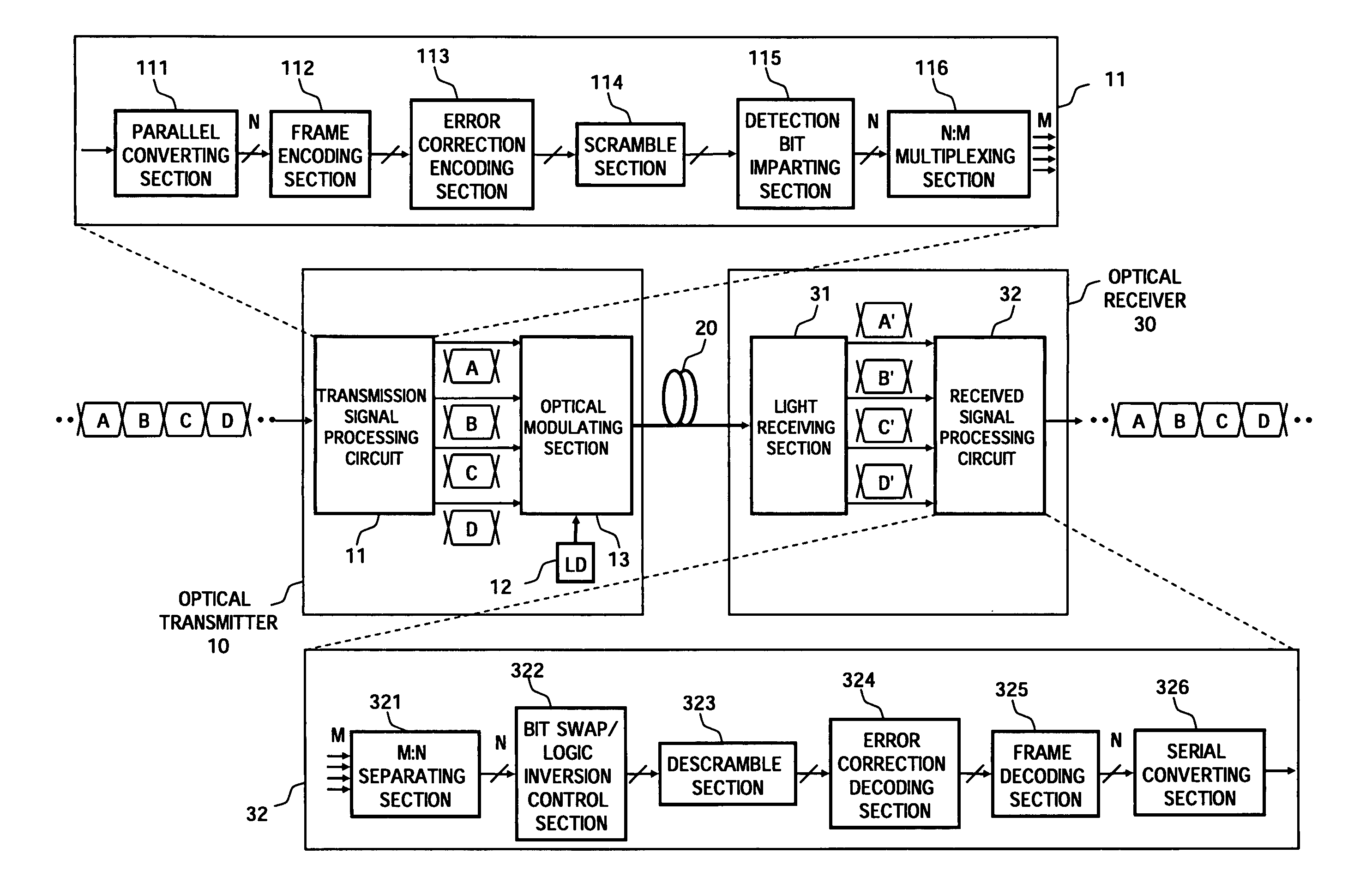
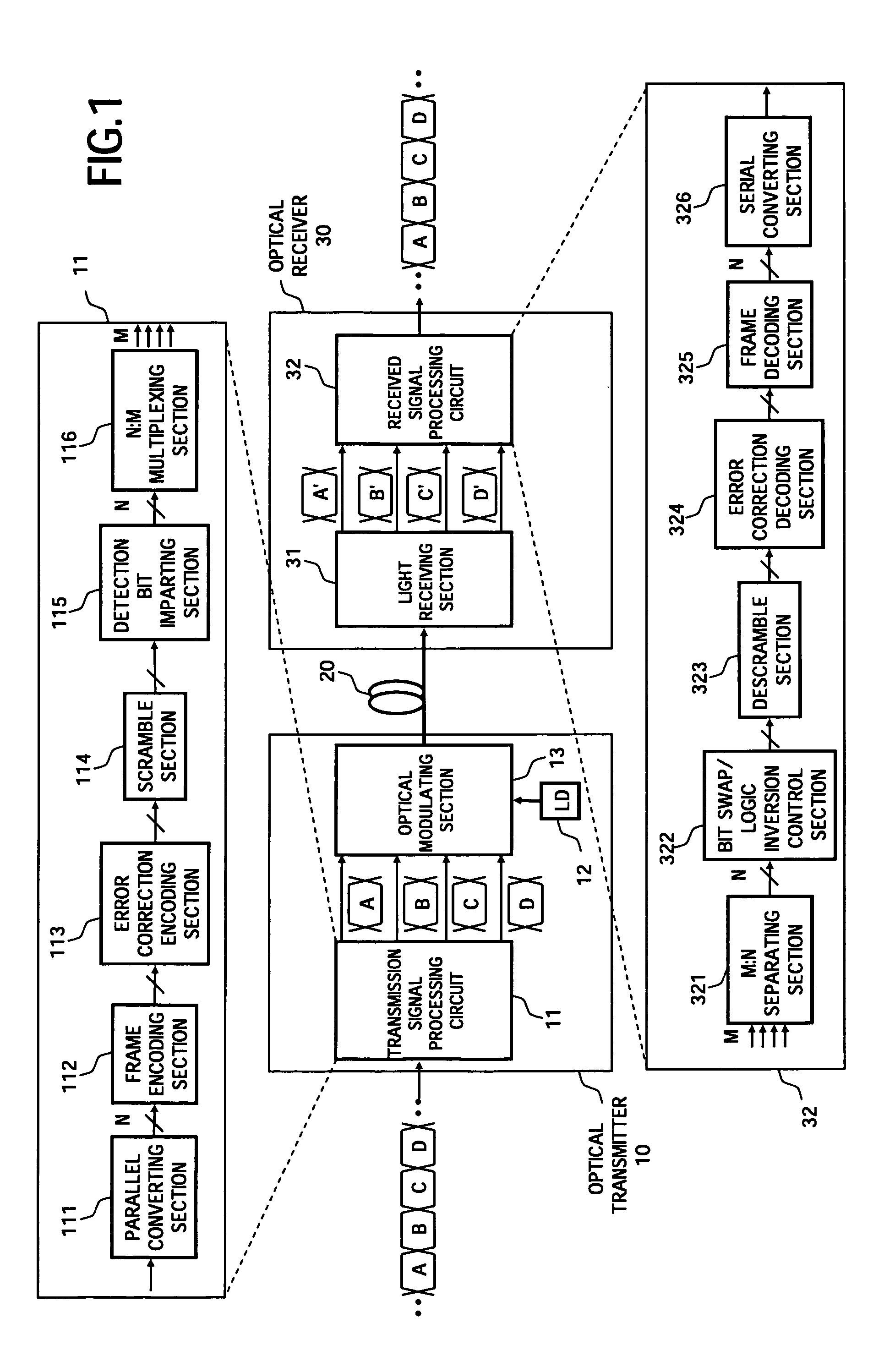
[0045]FIG. 1 is a block diagram showing the configuration of an optical transmission system according to the present invention.
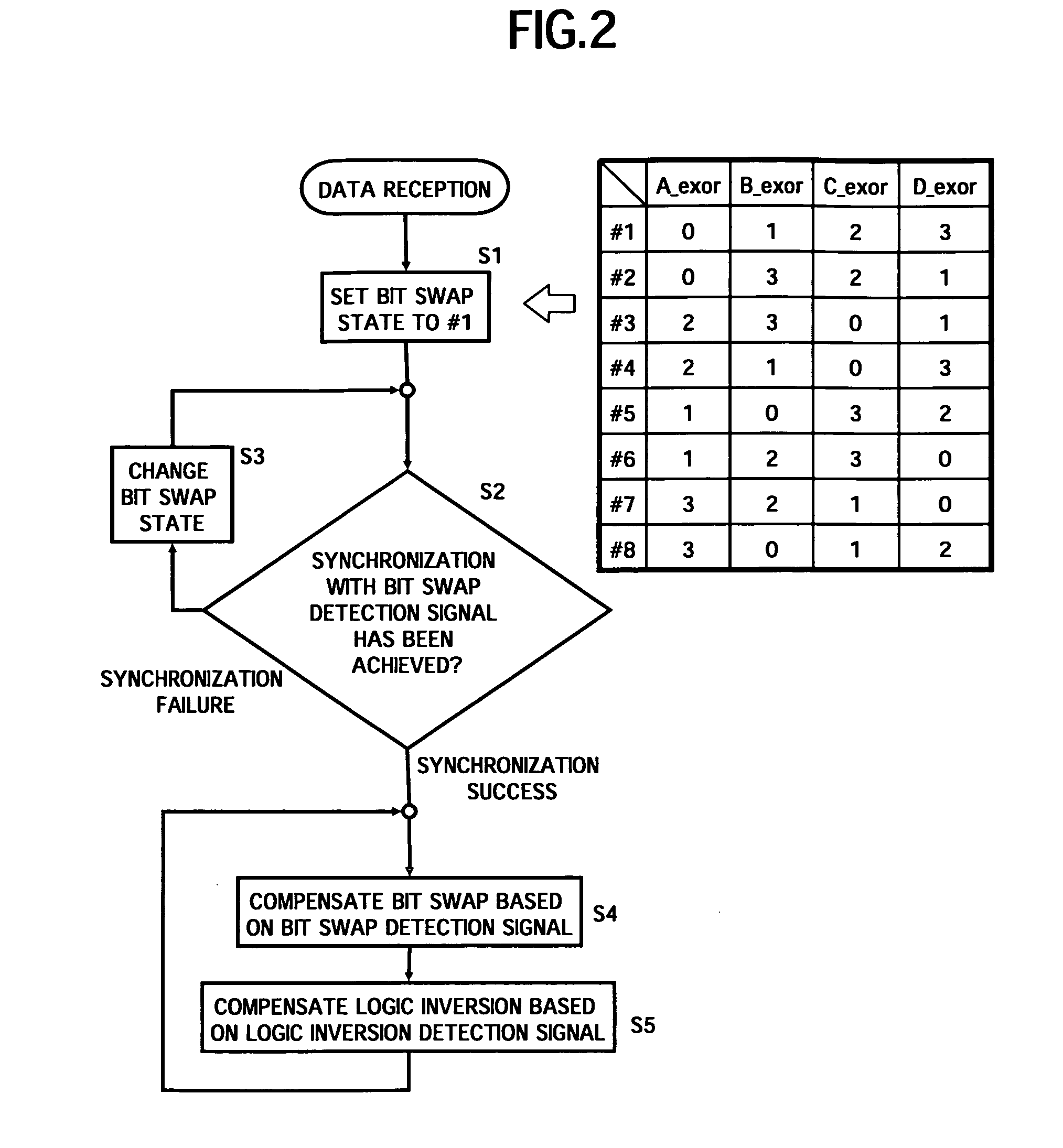
[0046]In the optical transmission system of the first embodiment, for example in a system capable of transmitting information of 4 bits (16-valued) or more within one symbol time, the occurrence of the above-described logic inversion and bit swap is detected on a reception side by using a predetermined detection bit imparted on a transmission side, and the logic inversion and the bit swap are compensated according to the detection result, by combining the multivalue modulation format and the polarization multiplexing system. In the configuration example in FIG. 1, an optical transmitter 10 comprising a transmission signal processing circuit 11, a light source (LD) 12, and an optical modulating section 13 is connected to an optical receiver 30 comprising a light receiving section 31 and a received signal processing circuit 32, via a transmission line 20. The ...
second embodiment
[0079]Next is a description of the present invention.
[0080]FIG. 7 is a block diagram showing the configuration of the optical transmission system according to the second embodiment of the present invention.
[0081]In FIG. 7, in the optical transmission system, when the coherent receiving system is applied to the optical receiver 30, in the aforementioned configuration of the first embodiment (FIG. 1), detection and compensation of the dynamic bit swap and logic inversion occurring due to phase fluctuation or the like in the local oscillator light used for coherent reception can be performed more reliably, by defining a sub-frame shorter than an error correction frame for a transmission signal, and arranging the same detection bit as in the first embodiment at the head of the sub-frame.
[0082]Specifically, the point where the configuration of this optical transmission system is different from the case of the first embodiment is that a sub-frame encoding section 117 is provided, instead ...
third embodiment
[0087]Next is a description of the present invention.
[0088]FIG. 9 is a block diagram showing the configuration of the optical transmission system according to the third embodiment of the present invention.
[0089]In the optical transmission system according to the third embodiment, for example, for a system that can transmit 2 bits (4-valued) or more information within one symbol time by using the polarization multiplexing system or the multivalue modulation format, characteristic variations between transmission channels caused by the PDL or the like in the transmission line or the optical device are taken into consideration, and deterioration of the error correction performance at the time of reception is suppressed by allocating transmission data to each transmission channel so that the variations are averaged over all the transmission channels. In the configuration example of FIG. 9, an optical transmitter 10 comprising a transmission signal processing circuit 11″, a light source (...
PUM
 Abstract
Description
Claims
Application Information
 - Generate Ideas
- Intellectual Property
- Life Sciences
- Materials
- Tech Scout
- Unparalleled Data Quality
- Higher Quality Content
- 60% Fewer Hallucinations
Browse by: Latest US Patents, China's latest patents, Technical Efficacy Thesaurus, Application Domain, Technology Topic, Popular Technical Reports.
© 2025 PatSnap. All rights reserved.Legal|Privacy policy|Modern Slavery Act Transparency Statement|Sitemap|About US| Contact US: help@patsnap.com