System and method for securing surgical implant

a surgical implant and system technology, applied in the field of surgery, can solve the problems of unreliability of the final position of the jig hole with the im rod hole, the screw farthest from the im rod insertion hole is currently a difficult and time-consuming procedure, and the technique still requires a significant number of x-ray images

Inactive Publication Date: 2009-04-02
GENERAL ELECTRIC CO
View PDF10 Cites 53 Cited by
  • Summary
  • Abstract
  • Description
  • Claims
  • Application Information

AI Technical Summary

Benefits of technology

[0006]In one embodiment, a system for locating a transverse hole disposed at a predetermined location in a surgical implant inserted into a fractured bone of a patient and for drilling the fractured bone coaxially with the transverse hole is provided. The system comprises a first electromagnetic sensor unit coupled to the surgical implant, a surgical instrument for drilling a hole through the fractured bone coaxially with the transverse hole, an electromagnetic drive unit coupled to the surgical instrument for energizing the first electromagnetic sensor unit to transmit a signal, a second electromagnetic sensor unit configured for receiving the signal and a display unit coupled to the first and second electromagnetic sensor units for converting the signal into visual signals enabling a user to change the position of the surgical instrument to align the surgical instrument with the transverse hole of the surgical implant.

Problems solved by technology

The insertion of the screws farthest from the IM rod insertion hole is currently a difficult and time consuming procedure requiring numerous x-ray images.
External jigs have been tried with little success as inaccuracies in the jig leads to inaccuracy of the mounting between the jig and the IM rod, and deformations of the IM rod accumulate to cause the final jig hole positions to be unreliably aligned with the IM rod holes.
However these techniques still require a significant number of x-ray images to be obtained in order to first achieve a C-arm orientation that produces “perfect circles” in the images.

Method used


Image

  • System and method for securing surgical implant
  • System and method for securing surgical implant
  • System and method for securing surgical implant

Examples


Embodiment Construction

[0017]In the following detailed description, reference is made to the accompanying drawings that form a part hereof, and in which is shown by way of illustration specific embodiments, which may be practiced. These embodiments are described in sufficient detail to enable those skilled in the art to practice the embodiments, and it is to be understood that other embodiments may be utilized and that logical, mechanical, electrical and other changes may be made without departing from the scope of the invention. The following detailed description is, therefore, not to be taken in a limiting sense.

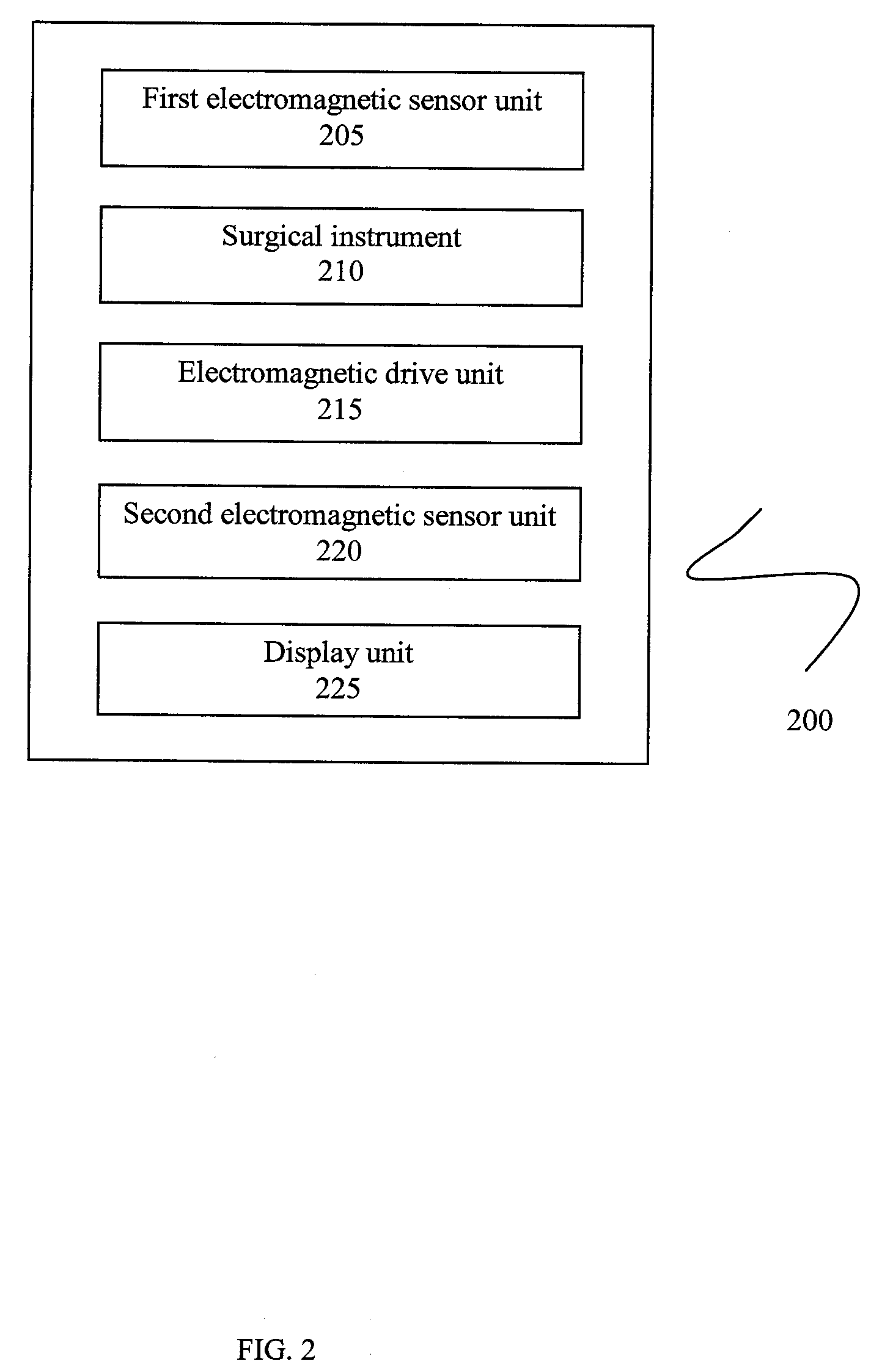
[0018]An embodiment of the invention provides a system and method for locating an electromagnetic sensor unit placed within a surgical implant, such as an intramedullary rod, used in orthopaedic surgery.

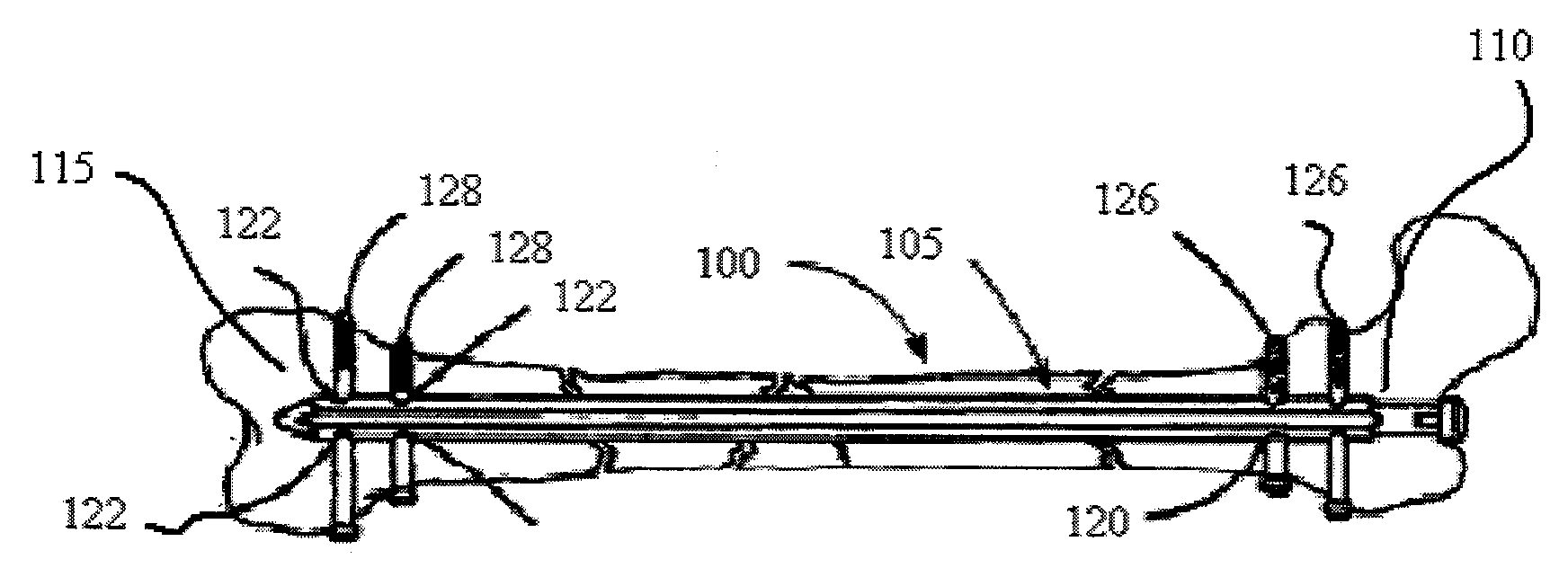
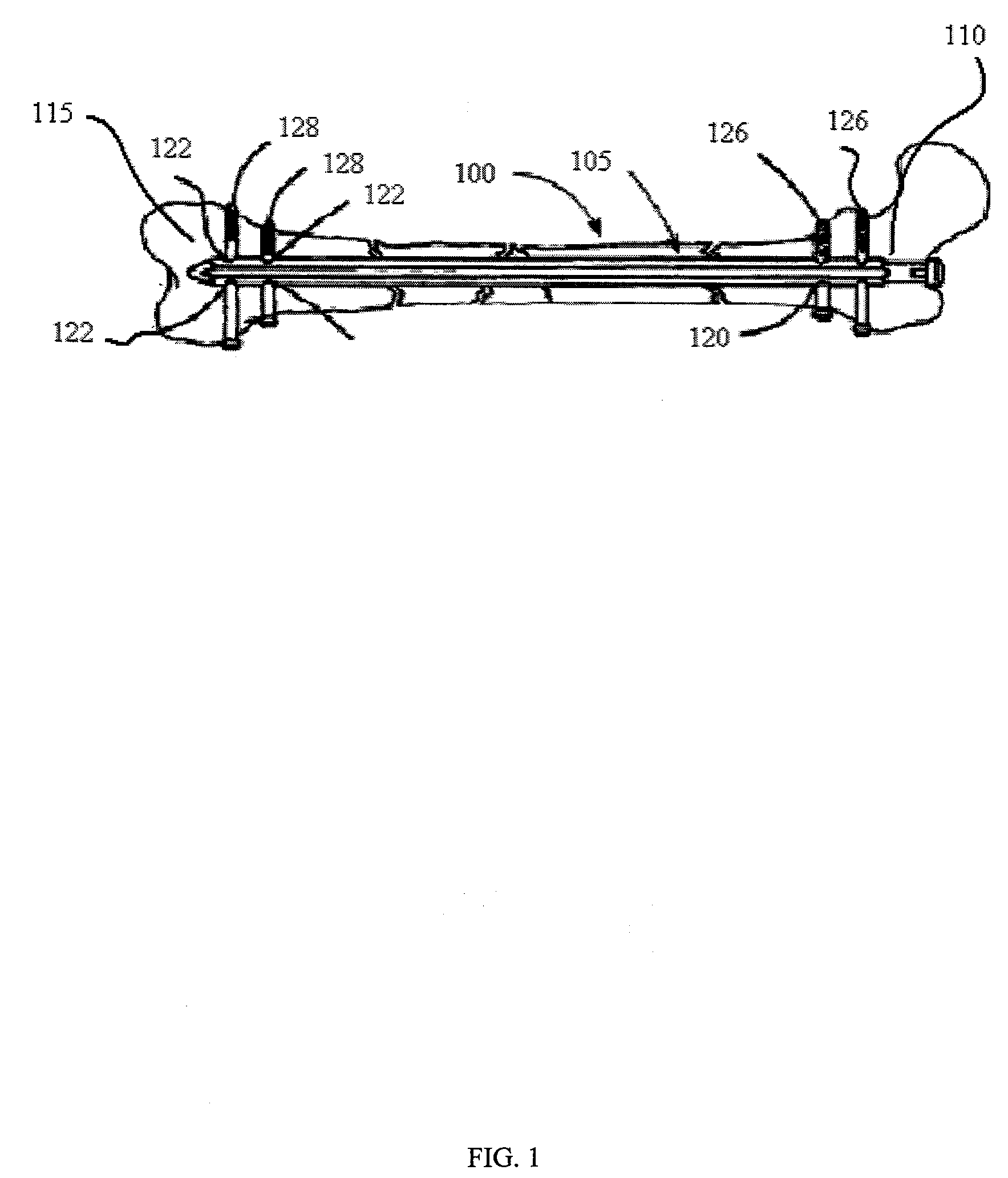
[0019]In FIG. 1, a broken long bone 100, for example, a broken femur, tibia, or humerus bone, is shown in which a conventional intramedullary rod 105 has been inserted into the interior region of...


PUM


Abstract

In one embodiment, a system for locating a transverse hole disposed at a predetermined location in a surgical implant inserted into a fractured bone of a patient and for drilling the fractured bone coaxially with the transverse hole is provided. The system comprises a first electromagnetic sensor unit coupled to the surgical implant, a surgical instrument for drilling a hole through the fractured bone coaxially with the transverse hole, the surgical instrument having a main axis disposed in parallel to the axis of the transverse hole, an electromagnetic drive unit coupled to the surgical instrument for energizing the first electromagnetic sensor unit to transmit a signal, a second electromagnetic sensor unit configured for receiving the signal and a display unit for converting the signal into visual signals enabling a user to change the position of the surgical instrument to align the surgical instrument with the transverse hole of the surgical implant.

Description

FIELD OF THE INVENTION[0001]The invention relates generally to the field of surgery, and in particular relates to techniques for aligning a surgical instrument with holes of a surgical implant.BACKGROUND OF THE INVENTION[0002]A current surgical treatment for fractures of the shaft of long bones (e.g., femur and tibia) is the insertion of an intramedullary rod (IM rod). The IM rods are relatively rigid devices inserted into one end of the bone and down the center canal of the bone shaft, such that the fracture site is bridged. Transverse holes in either end of the IM rod receive screws inserted transversely through the bone in order to lock the two bone fragments relative to one another. The insertion of the screws farthest from the IM rod insertion hole is currently a difficult and time consuming procedure requiring numerous x-ray images. An intraoperative x-ray machine (C-arm) is repeatedly fired and reoriented until it is exactly aligned with the transverse holes as evidenced by i...

Claims


Application Information

Patent Timeline
Patent Type & Authority Applications(United States)
IPC IPC(8): A61B17/00A61B5/05
CPCA61B5/06A61B17/1725A61B17/1707A61B5/4504
Inventor ANDERSON, PETER
Owner GENERAL ELECTRIC CO
Why Eureka
Try Eureka