Road Marking Recognition System

a recognition system and road marking technology, applied in the direction of navigation instruments, process and machine control, instruments, etc., can solve the problems of increasing the processing load of the device, reducing the recognition error ratio, and reducing the processing load and const of the devi

Inactive Publication Date: 2009-04-02
AISIN AW CO LTD +1
View PDF5 Cites 72 Cited by
  • Summary
  • Abstract
  • Description
  • Claims
  • Application Information

AI Technical Summary

Benefits of technology

[0009]Various exemplary implementations of the broad principles described herein provide a road marking recognition system in which a recognition error ratio is reduced by eliminating road markings that are difficult to detect as detection subjects in advance. Thus, the processing load and const of the device may be reduced by performing only required processing.

Problems solved by technology

However, because the temporary stop line is formed on the surface of the road traveled by vehicles, a part of the paint may peel away or become thin over time due to various causes such as friction from the tires.
Thus, over time the temporary stop line may be detected erroneously or may be difficult to detect.
Moreover, when all road markings, including road markings that are likely to be recognized erroneously, are detected, the processing load of the device increases and a control unit for performing image processing must be provided separately.
As a result, the entire device becomes more expensive, hindering widespread use of such vehicle control devices using cameras.

Method used


Image

  • Road Marking Recognition System
  • Road Marking Recognition System
  • Road Marking Recognition System

Examples


second embodiment

[0116]Next, an exemplary driving support method, for example in the form of a processing program executed by the navigation ECU 6 of the driving support device having the constitution described above, will be described on the basis of FIG. 14. The exemplary method may be implemented, for example, by one or more components of the above-described devices. However, even though the exemplary structure of the above-described devices may be referenced in the description, it should be appreciated that the structure is exemplary and the exemplary method need not be limited by any of the above-described exemplary structure.

[0117]The driving support processing program performs control to detect the “thick broken line” road marking from an image captured by the rear camera 3 as the vehicle 2 travels along a road surface, detect the distance from the detected road marking to the vehicle and a control subject, and assist the driver on the basis of this distance. Note that the program shown in t...

third embodiment

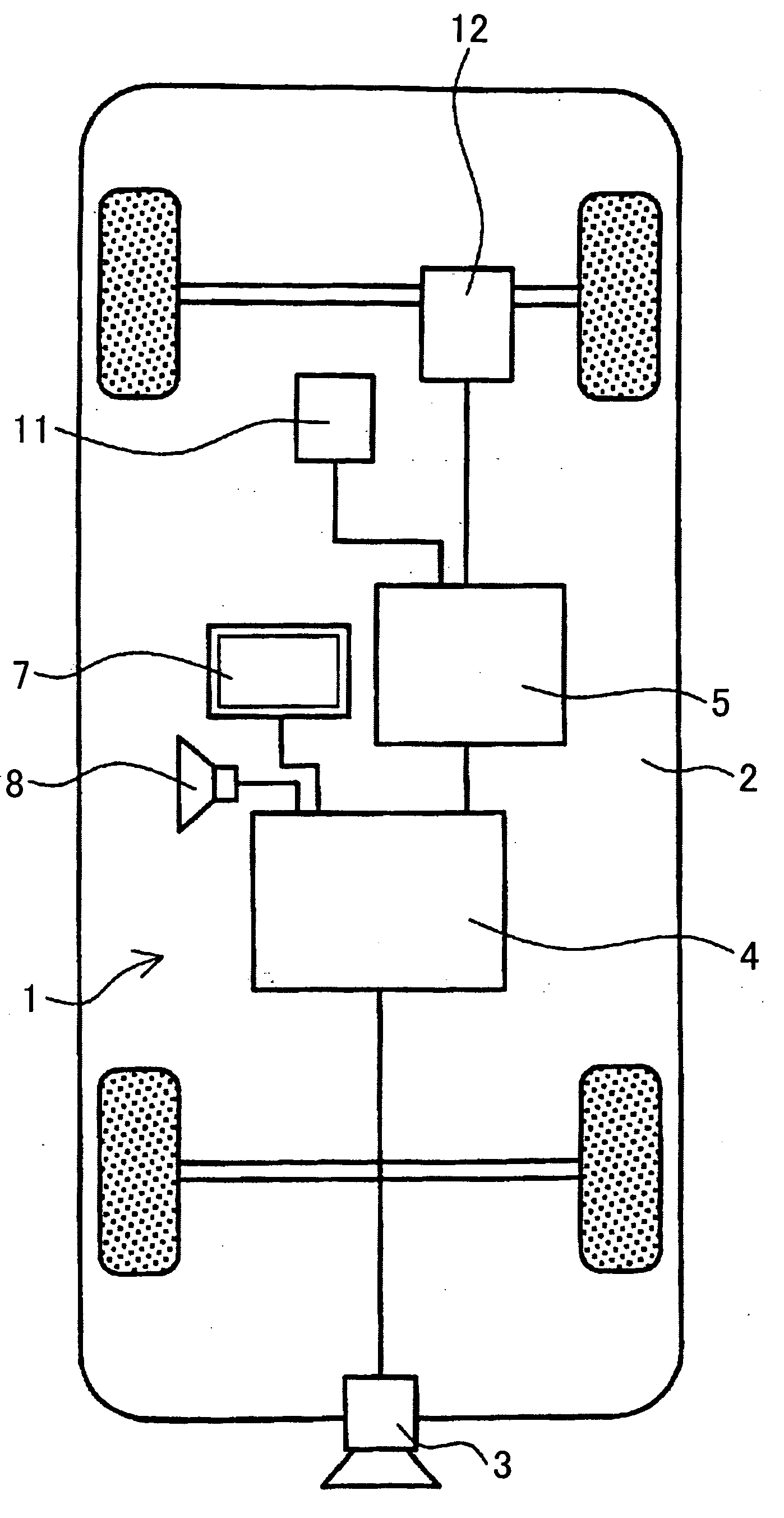
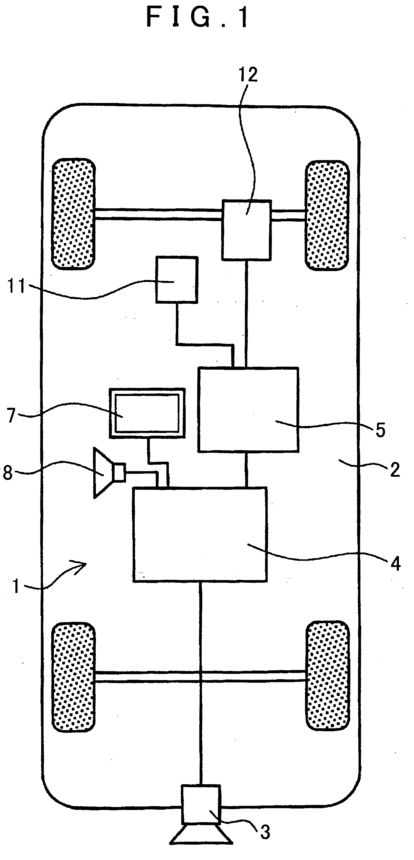
[0151]First, an outline of the structure of the driving support device 100 according to this example will be described using FIG. 17. FIG. 17 is a schematic diagram of the driving support device 100 according to the As shown in FIG. 17, the driving support device 1 according to this example includes the front camera 101, rear camera 3, navigation device 4, vehicle ECU 5, and so on, which are disposed on the vehicle 2.

[0152]The front camera 101 employs a solid state imaging element such as a CCD, for example, and is attached near the upper center of a number plate attached to the front of the vehicle 2 such that a sight line direction faces slightly downward from the horizon. Thus, the front camera 101 captures images of traffic lights, road signs, road markings, and so on disposed in front of the vehicle 2.

first embodiment

[0153]The rear camera 3, navigation device 4, vehicle ECU 5, and all structures other than the front camera 101 are similar to those of the driving support device 1 and hence description thereof has been omitted.

[0154]In the driving support device 100 according to the third embodiment, enlargement of the control subject and an improvement in the road marking recognition ratio can be realized in the following manner on the basis of images captured by the front camera 101.

[0155]For example, when it is determined on the basis of an image captured by the front camera 101 that traffic lights positioned at an intersection ahead are red, travel guidance and vehicle drive control (S111 to S14, S112 to S115) corresponding to the “intersection” control subject are performed as described above, and in addition, a warning that the traffic lights at the intersection are red can be issued, and the brake actuator 11 can be controlled to stop the vehicle 2 in front of the intersection.

[0156]Furthe...


PUM


Abstract

Systems, methods, and programs capture an image of a periphery of a vehicle. The systems, methods, and programs, store predetermined patterns representing conditions of road markings formed on a road surface, detect a road marking on the basis of the captured image, and compare the detected road marking to the predetermined patterns. If the detected road marking matches one of the predetermined patterns, the systems, methods, and programs execute a predetermined action associated with the matching predetermined pattern.

Description

INCORPORATION BY REFERENCE[0001]This application is a National Phase of International Patent Application No. PCT / JP06 / 315491, filed Aug. 4, 2006, which claims priority of Japanese Patent Application Nos. 2005-228900, filed Aug. 5, 2005, and 2006-212481, filed Aug. 3, 2006. The disclosures of these applications are incorporated herein by reference in their entirety.BACKGROUND[0002]1. Related Technical Fields[0003]Related technical fields include road marking recognition systems that recognize road markings formed on a road surface on the basis of an image captured by imaging means.[0004]2. Related Art[0005]Driving support devices that prevent traffic accidents by obtaining information relating to vehicle travel (such as road information obtained from map data of a navigation device and a current position identified by GPS or the like) notifying a driver thereof, providing driving assistance, and even intervening in the driving, have been proposed.[0006]These driving support devices n...

Claims


Application Information

Patent Timeline
Patent Type & Authority Applications(United States)
IPC IPC(8): G01C21/00
CPCG01C21/26G05D1/0244G06K9/00798G06K9/00818G05D2201/0213G08G1/096725G08G1/09675G08G1/096783G08G1/167G08G1/096716G06V20/588G06V20/582
Inventor ISHIKAWA, TOMOAKINAKAMURA, MASAKIAISAKA, OSAMUKANBA, MOTOKINAKAMURA, MOTOHIRO
Owner AISIN AW CO LTD
Why Eureka
Try Eureka