
Insulation of an Aircraft Fuselage Structure

Active Publication Date: 2009-04-09
AIRBUS OPERATIONS GMBH
View PDF17 Cites 28 Cited by
  • Summary
  • Abstract
  • Description
  • Claims
  • Application Information

AI Technical Summary

Benefits of technology

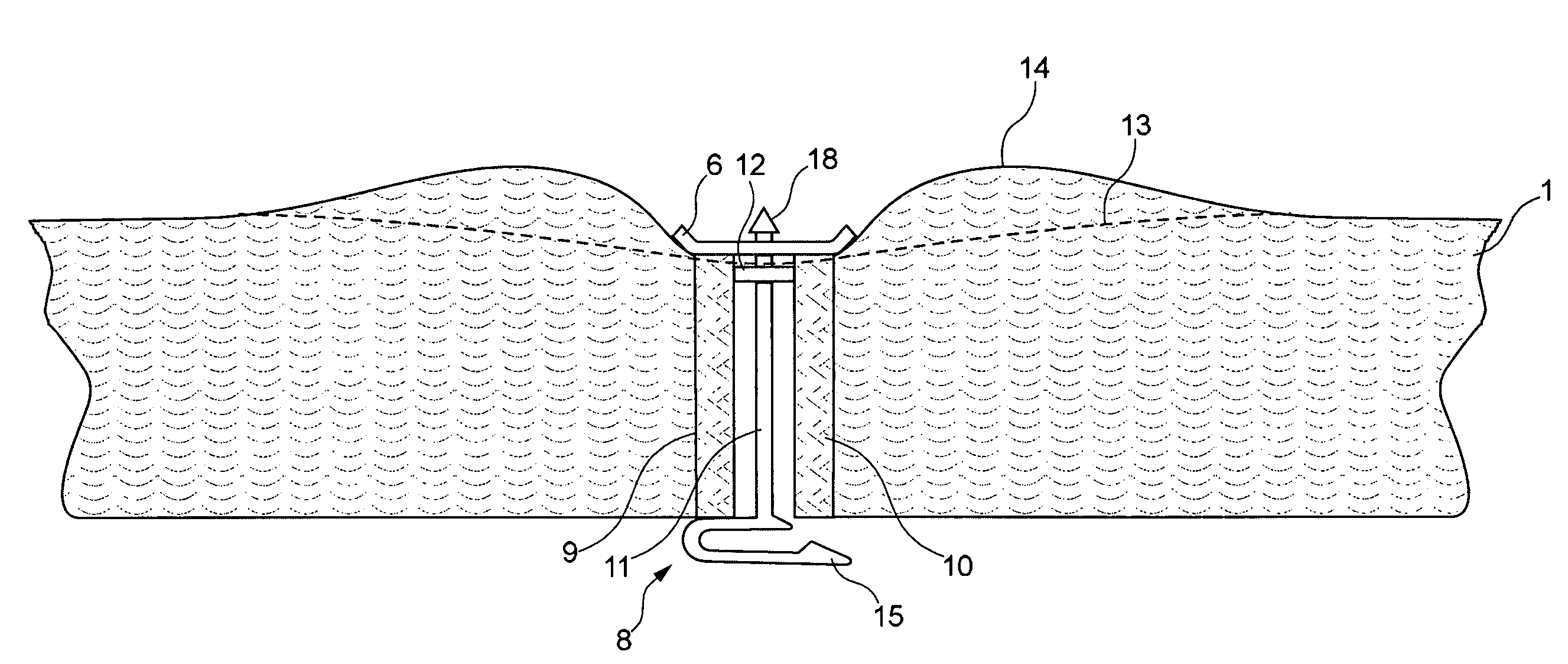
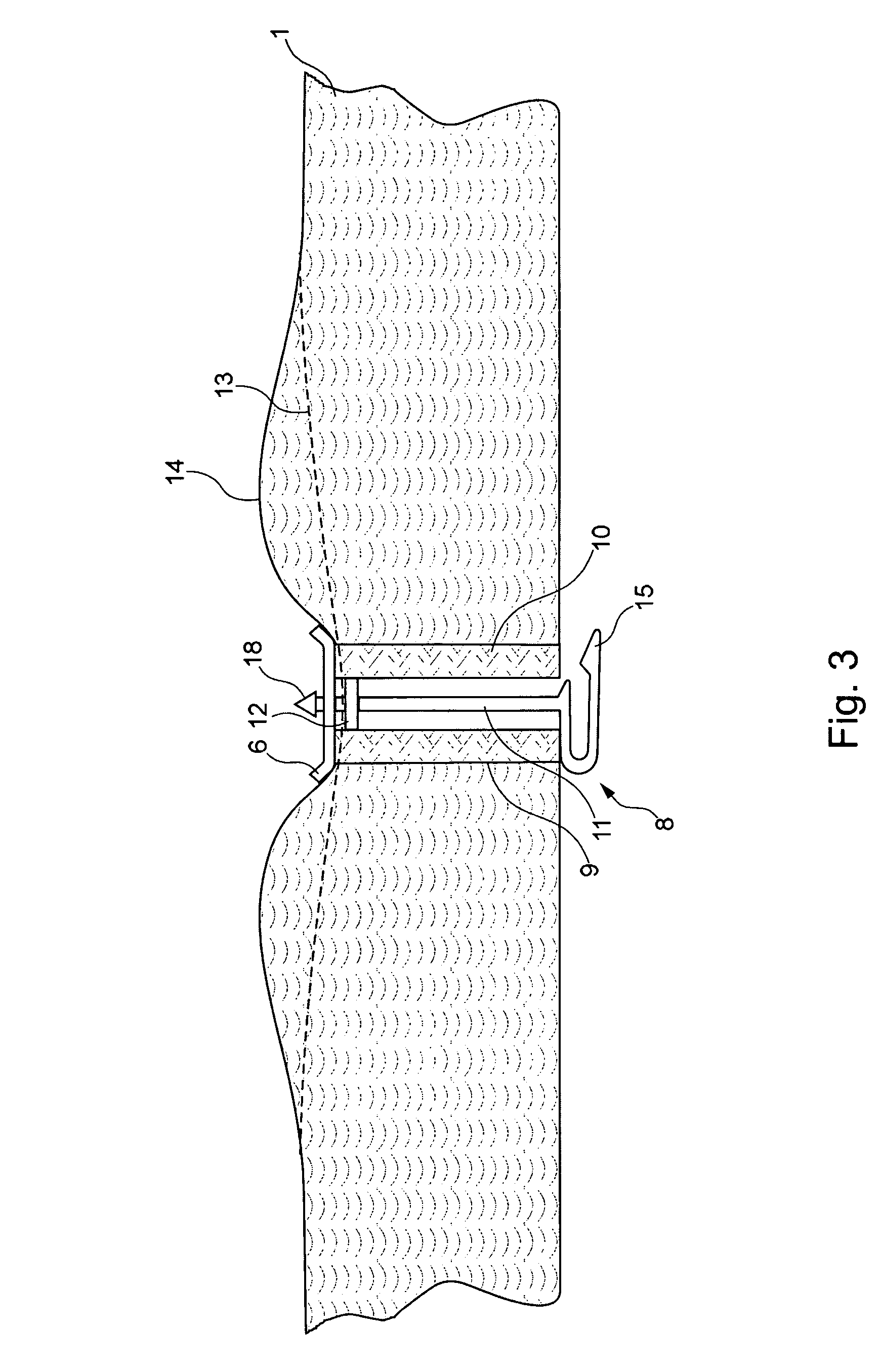
[0008]Due to the fact that the fastening clips laterally protrude over the lateral border of the insulating mat, it can be ensured that the insulating mat can be fastened to a fuselage structure, particularly the frames, by means of these fastening clips without affecting the insulating mat itself. For example, the insulating mat may be arranged in a frame panel, wherein the fastening clips of the first surface are positioned on the frames bordering the frame panel and fastened thereto. This makes it possible to simultaneously eliminate the acoustic weak point in the form of the gap resulting between the frame insulating mat and the panel insulating mat if the insulating mat is conventionally installed.
[0024]In order to allow quick attaching of the abutment elements on the shaft the shaft can have an arrangement at its second end, the arrangement having a multitude of barb elements which are adapted to secure an abutment element such as for example a fastening disk for fastening an insulation mat on the shaft. In this manner, an abutment element such as for example a fastening disk can be easily slid on to the second end of the shaft until it abuts the limit stop wherein the barb elements prevent an undesired releasing of the abutment elements from the shaft.

Problems solved by technology

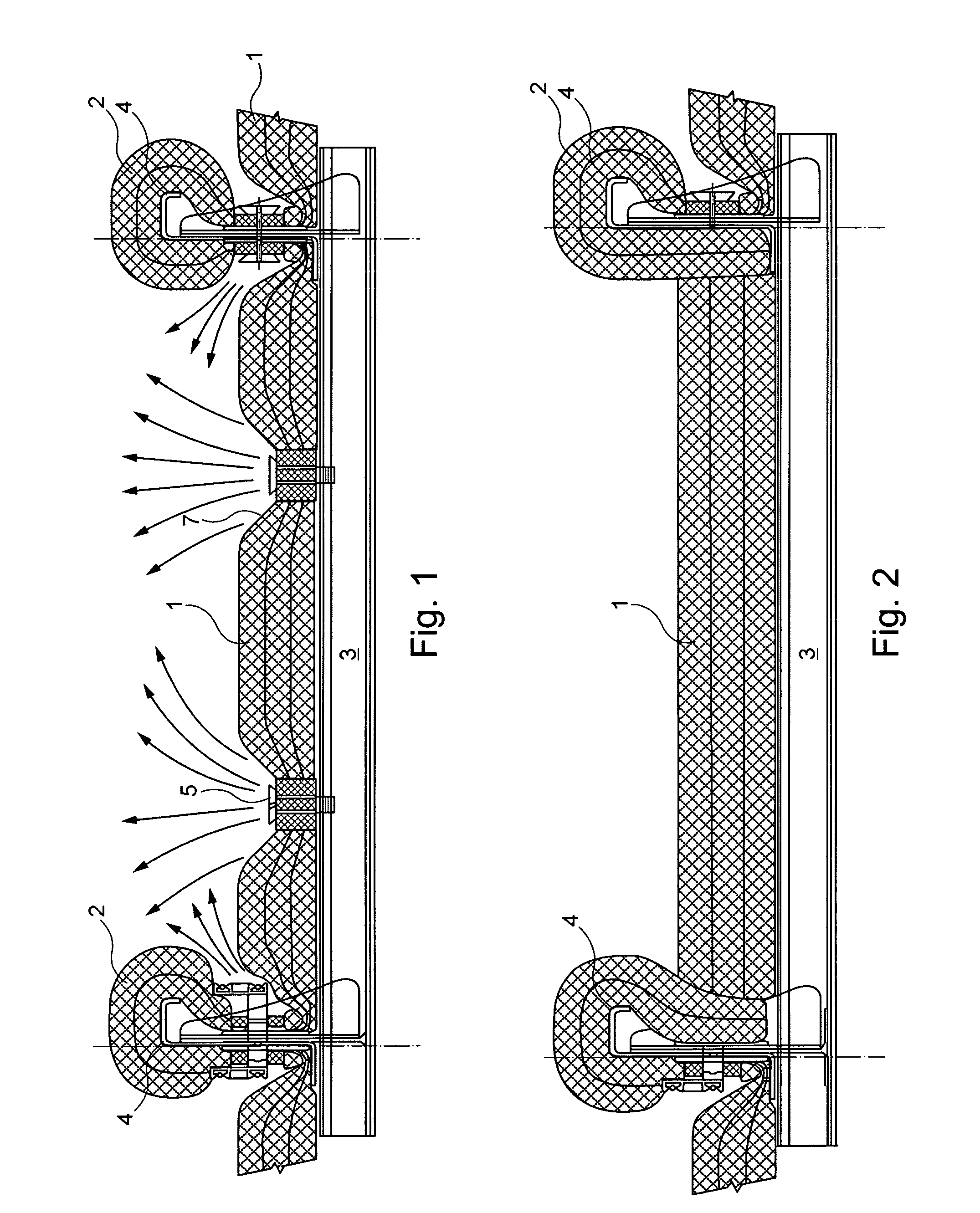
In these regions, however, where the insulation is compressed, the acoustic effect of the insulation is inferior to the same quantity of insulating material in its original thickness.
In addition, the cover foil of the insulating mats is stretched over the disks fastened on the fastening needles such that the cover foil is disadvantageously subjected to vibrations originating from the aircraft fuselage via the fastening needles and the disks.
The thusly induced vibrations are emitted in the form of noise waves via the funnel that results from the compression of the cover foil and is clearly visible in FIG. 1 similar to a loudspeaker such that the noise contamination may increase.
FIG. 1 furthermore shows that the insulating mat is substantially compressed in the region of the frames such that undesirable acoustic and thermal bridges are also created at these locations.

Method used


Image

  • Insulation of an Aircraft Fuselage Structure
  • Insulation of an Aircraft Fuselage Structure
  • Insulation of an Aircraft Fuselage Structure

Examples


Embodiment Construction

[0036]A conventionally sound-insulated aircraft fuselage structure is initially described below with reference to FIG. 1 in order to better comprehend the invention. The aircraft fuselage structure consists of stringers 3 that extend in the longitudinal direction of an aircraft fuselage and frames 4 that carry the stringers 3 and extend perpendicular thereto. The aircraft fuselage structure is insulated by means of panel insulation 1 in the form of an insulating mat 1 in the frame panels situated between the respective frames 4. The frames 4 are also insulated with the aid of insulating mats 2 that are wound around the frames 4 and fastened thereon with the aid of suitable fastening means 5. The panel insulation 1 is installed with fastening means 5 in the form of so-called “fir trees”5, i.e., fir tree-shaped fastening needles, that are attached to the stringers 3. These “fir trees”5 are pushed through the insulation such that for fixation of the panes insulation 1 fastening disks 6...


PUM


Abstract

An insulating mat for the sound insulation of an aircraft fuselage structure that is composed of frames and stringers extending transverse to the frames, to a fastener means for fastening an insulating mat on an aircraft fuselage structure such that acoustic bridges are prevented. An insulating kit is also provided that comprises at least one insulating mat as well as at least one fastener. The insulating mat features a plurality of fastening clips that are fixed on a first surface of the insulating mat and laterally protrude over the border of the insulating mat.

Description

RELATED APPLICATIONS[0001]This application claims the benefit of the filing date of U.S. Provisional Patent Application No. 60 / 747,470 filed May 17, 2006, and of the German Patent Application No. 10 2006 023 209.7 filed May 17, 2006, the disclosures of which are hereby incorporated herein by reference.TECHNICAL FIELD[0002]The present invention generally pertains to the technical field of acoustics. The invention specifically pertains to a specially designed insulating mat for insulating an aircraft fuselage structure relative to the passenger cabin or the cargo compartment formed by said aircraft fuselage structure in acoustic and partly also in thermic respects. In addition, the invention pertains to a specially designed fastening means for fastening an insulating mat on an aircraft fuselage structure in such a way that only few acoustic bridges, if any, are created. The present invention furthermore pertains to an insulating kit that comprises at least one inventive insulating mat...

Claims


Application Information

Patent Timeline
IPC IPC(8): B64C1/40B64C1/12
CPCB64C1/403B64C1/40
Inventor BOOCK, KLAUSGROCHULLA, RALFBECKER, CHRISTIAN
Owner AIRBUS OPERATIONS GMBH
Learn More