Projection-type image display apparatus, lighting apparatus and lighting method realizing an extended lifetime

a technology of projection-type images and display apparatuses, which is applied in the direction of electric variable regulation, process and machine control, instruments, etc., can solve the problem of hard to say that the brightness of the lamp is ensured during the operation of the lamp at the rated power, and achieve the effect of sufficient brightness and extended lamp li

Inactive Publication Date: 2009-04-09
PANASONIC CORP
View PDF9 Cites 15 Cited by
  • Summary
  • Abstract
  • Description
  • Claims
  • Application Information

AI Technical Summary

Benefits of technology

[0011]The present invention has been achieved in light of the above issues, and an aim thereof is to provide a projection-type image display apparatus, a lighting apparatus and a lighting method that ensure a sufficient brightness during lamp operation at rated power, while also achieving an extended lamp lifetime.

Problems solved by technology

However, although continually or periodically performing lighting at a low power according to the above technology reduces the heat load on the lamp and realizes and extended lamp lifetime, it is hard to say that a sufficient brightness is ensured during operation of the lamp at the rated power.

Method used


Image

  • Projection-type image display apparatus, lighting apparatus and lighting method realizing an extended lifetime
  • Projection-type image display apparatus, lighting apparatus and lighting method realizing an extended lifetime
  • Projection-type image display apparatus, lighting apparatus and lighting method realizing an extended lifetime

Examples


embodiment 1

[0058]1. Front Projection-Type Image Display Apparatus

[0059]The following describes a front projection-type image display apparatus (hereinafter, called a “liquid crystal projector”) pertaining to the present invention with reference to the drawings.

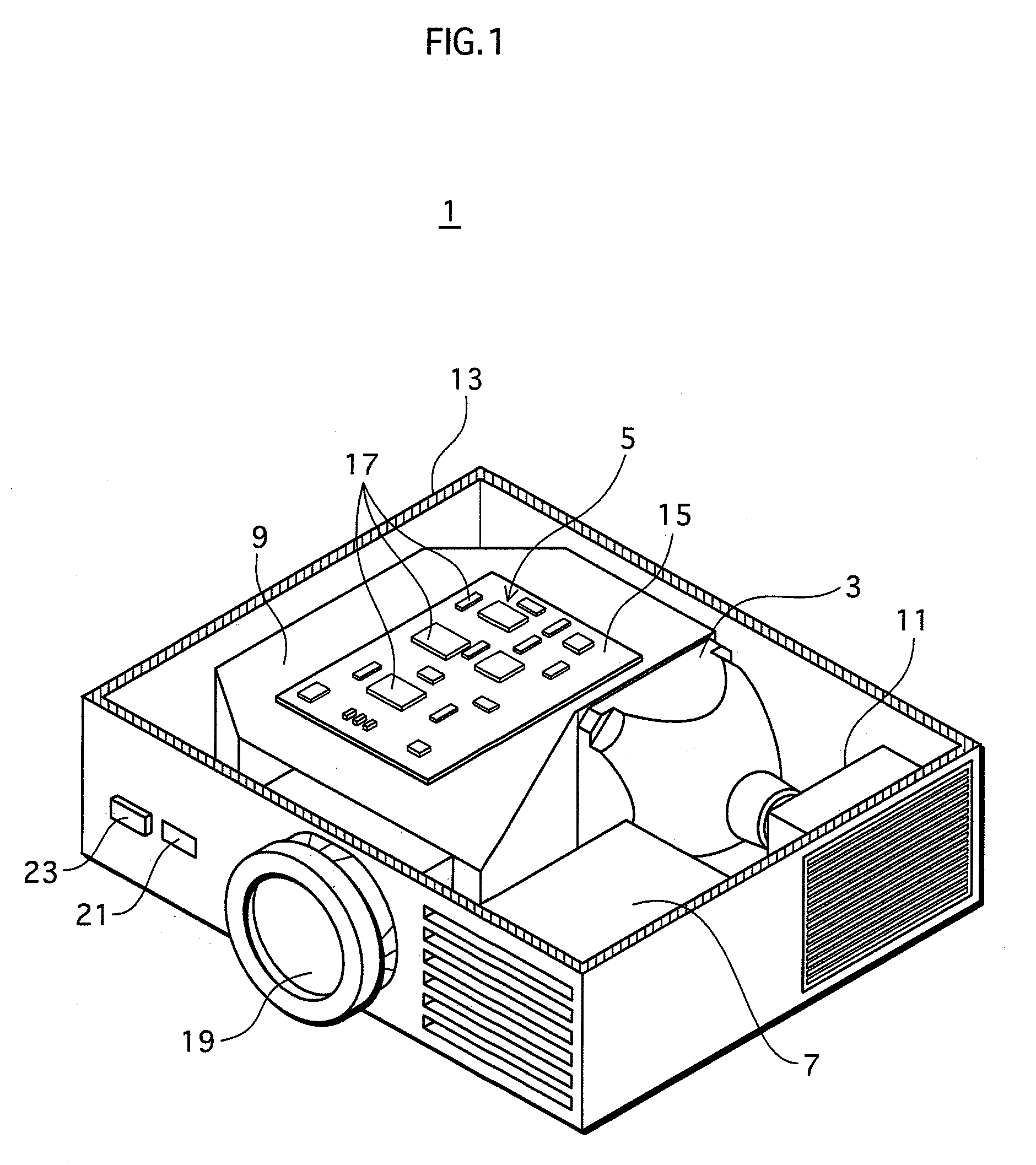
[0060]FIG. 1 is a partially cut away perspective view of the liquid crystal projector pertaining to the present embodiment.

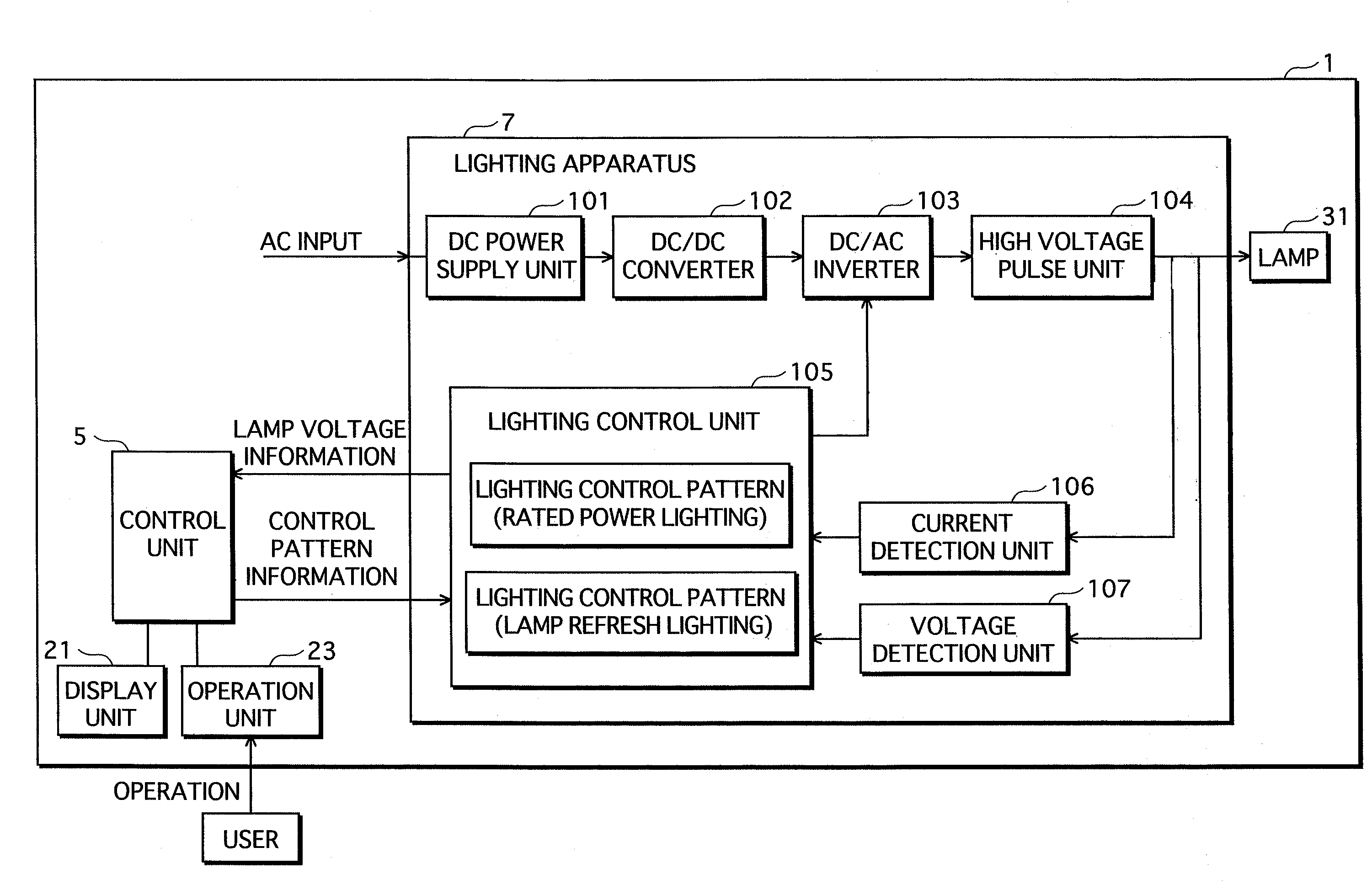
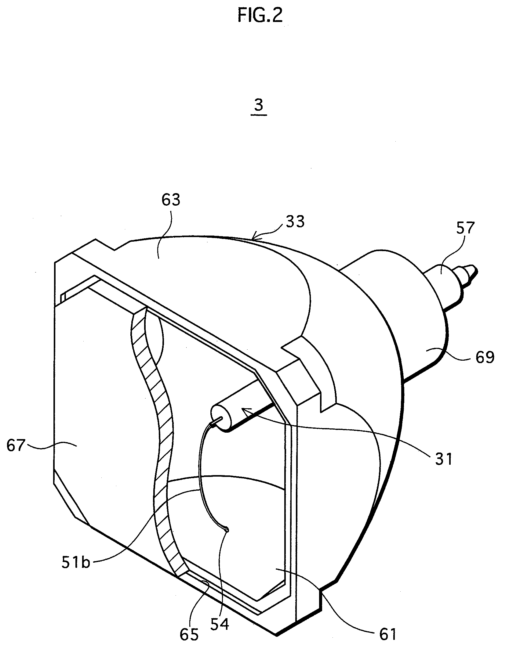
[0061]As shown in FIG. 1, a liquid crystal projector 1 includes a lamp unit 3 in which a lamp (not depicted) is provided, a control unit 5, a lighting apparatus 7 for lighting the lamp, a lens unit 9 in which a condensing lens, a transmission-type color liquid crystal display plate, and a drive motor are provided, a cooling fan 11, etc., all of which are arranged inside a casing 13.

[0062]In the liquid crystal projector 1, light emitted from the lamp unit 3 is condensed by the condensing lens etc. arranged in the lens unit 9, and transmitted through the color liquid crystal display plate arranged in the optical path. ...

embodiment 2

[0170]In embodiment 1, the timing for performing lamp refresh processing is determined according to whether the lamp voltage has reached a predetermined voltage value (i.e., by detecting the lamp voltage). However, the timing for performing lamp refresh processing may be determined according to the cumulative lighting time, the illuminance of the lamp, or the amount of change in the lamp voltage. Also, lamp refresh processing may be performed at the determination of the user, regardless of the condition of the lamp.

[0171]In embodiment 2, the timing for performing lamp refresh processing is determined according to whether the cumulative lighting time has reached a set time (i.e., by detecting the cumulative lighting time).

[0172]1. Structure

[0173]In step S5 of the flowchart shown in FIG. 9 that was described in embodiment 1, the lighting control unit of embodiment 2 judges the cumulative lighting time instead of the lamp voltage Vla.

[0174]The set time used as a reference is a cumulati...


PUM


Abstract

A projection-type image display apparatus includes a high pressure discharge lamp, which utilizes the halogen cycle, and a lamp lighting apparatus that controls lighting of the high pressure discharge lamp. The lamp lighting apparatus performs lamp refresh processing to improve a lamp property. The lamp refresh processing involves performing low power lighting of the high pressure discharge lamp by changing the lighting power of the high pressure discharge lamp to a value that is lower than the rated power, and thereafter performing high power lighting of the high pressure discharge lamp by changing the lighting power to a value that is higher than the lighting power during the low power lighting.

Description

[0001]This application -is based on application No. 2007-261799 filed in Japan, the content of which is hereby incorporated by reference.BACKGROUND OF THE INVENTION[0002]1. Field of the Invention[0003]The present invention relates to a projection-type image display apparatus using a high pressure discharge lamp as a light source, a lighting apparatus, and a lighting method.[0004]2. Description of the Related Art[0005]High pressure discharge lamps (hereinafter, simply called “lamps”) used as light sources in projection-type image display apparatuses include a discharge container, a light-emitting material enclosed in a discharge space in the discharge container, and a pair of electrodes provided such that the ends thereof oppose each other in the discharge space. In addition to the light-emitting material, a halide is enclosed in the discharge space, and the halogen cycle that occurs during sustained lighting is used to suppress the consumption of the electrodes. In such lamps, elect...

Claims


Application Information

Patent Timeline
Patent Type & Authority Applications(United States)
IPC IPC(8): H05B41/36
CPCH05B41/2886Y02B20/208Y02B20/202H05B41/2928Y02B20/00
Inventor YAMADA, GOONO, SYUNSUKE
Owner PANASONIC CORP
Why Eureka
Try Eureka