Liquid optics zoom lens and imaging apparatus

a liquid optics and zoom lens technology, applied in the field of optical zoom lens system, can solve the problems of adding size, weight and cost, affecting the use of zoom and focus lens system with moving lens group, so as to achieve the effect of reducing light requirements, long focal length and high light sensitivity

Inactive Publication Date: 2009-04-09
MONUMENT PEAK VENTURES LLC
View PDF36 Cites 42 Cited by
  • Summary
  • Abstract
  • Description
  • Claims
  • Application Information

AI Technical Summary

Benefits of technology

[0014]In one embodiment, an objective zoom lens system employing liquid optics has a focal length zoom region from about 5.9 mm to 45.0 mm. This embodiment was selected as providing a reasonably wide angle lens with a reasonably long focal length, yet maintaining a reasonable diameter lens at a reasonable length. In addition, apertures of F / 2.8 to F / 4.0 are acceptable for use with charge-coupled device (CCD) and complimentary metal-oxide-semiconductor (CMOS) detectors which have lower light requirements thus higher light sensitivity.
[0015]Benefits include only one movable zoom lens group and one or more liquid lens cells to provide zooming with less mechanical complexity, size and weight. In addition, reliability may improve when used over an extended period of time.
[0016]Axial position adjustment of the zoom lens group and variation of the surface shape between the liquids of one or more liquid lens cells provide zooming. Axial adjustment of the zoom lens group or shape variation in the liquid lens cell (or both), provides focusing and compensation for temperature induced effects such as image defocus and aberration variation which uncompensated may cause image quality degradation.

Problems solved by technology

However, there are intrinsic disadvantages associated in using zoom and focus lens systems with moving lens groups.
In particular, having moving zoom lens groups implies the need for complex mechanically moving parts.
This system complexity may add size, weight and cost and may make the system operation unreliable over a period of time.
These disadvantages together with undesirable limitations, such as a limited range of focal lengths, the inability to focus adequately over the entire focal length range, the inability to focus on close objects, the lack of adequate optical performance over the entire focal length range and focus distance, are present in some previously available zoom lenses having at least two moving zoom lens groups.

Method used


Image

  • Liquid optics zoom lens and imaging apparatus
  • Liquid optics zoom lens and imaging apparatus
  • Liquid optics zoom lens and imaging apparatus

Examples


Embodiment Construction

[0023]In the following description of preferred embodiments, reference is made to the accompanying drawings that form a part hereof, and in which is shown by way of illustration specific embodiments in which the invention may be practiced. It is to be understood that other embodiments may be utilized and structural changes may be made without departing from the scope of the invention.

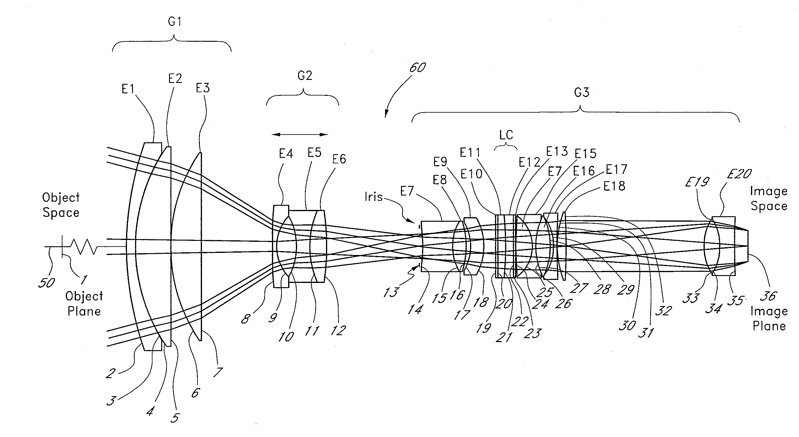
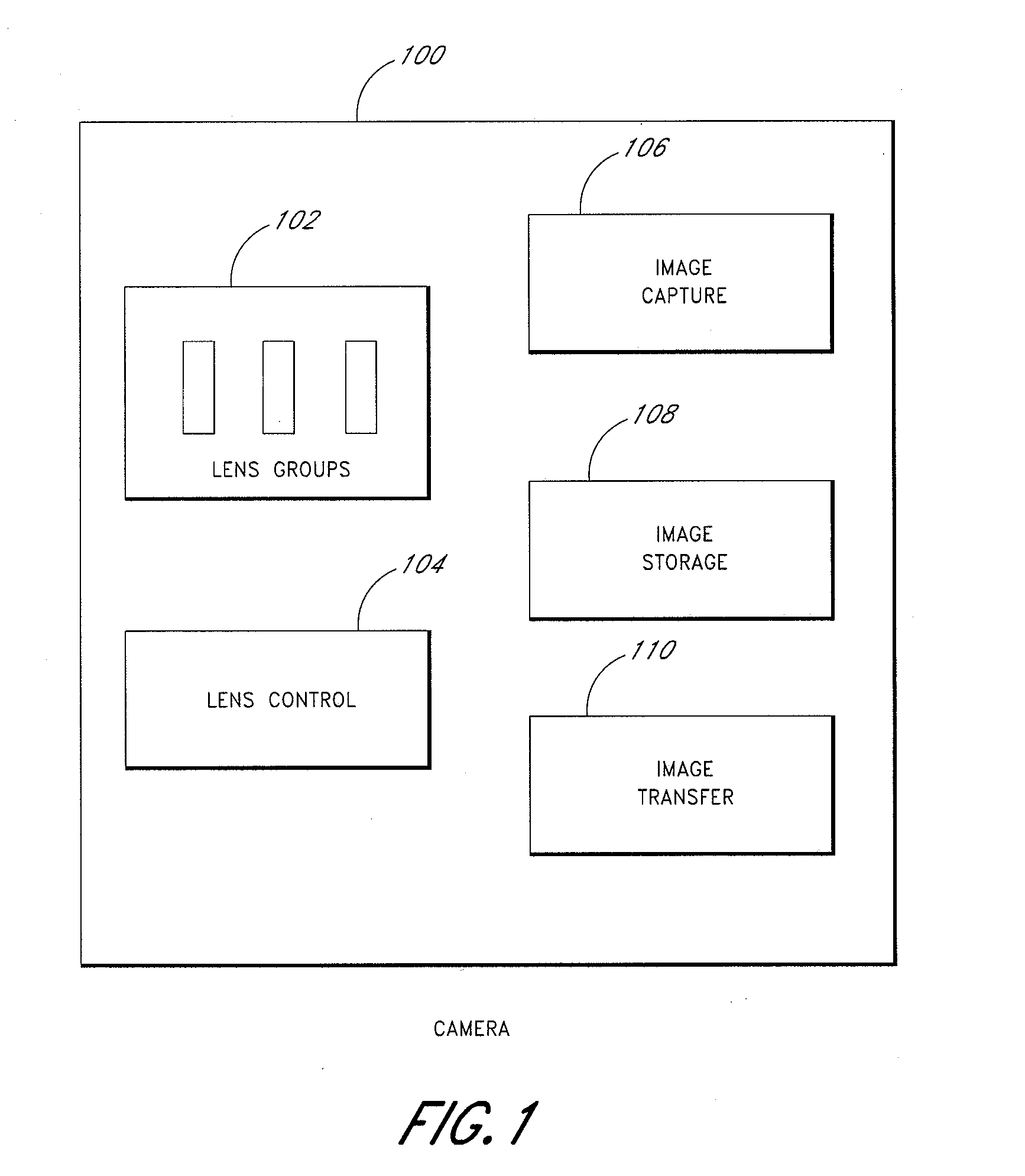
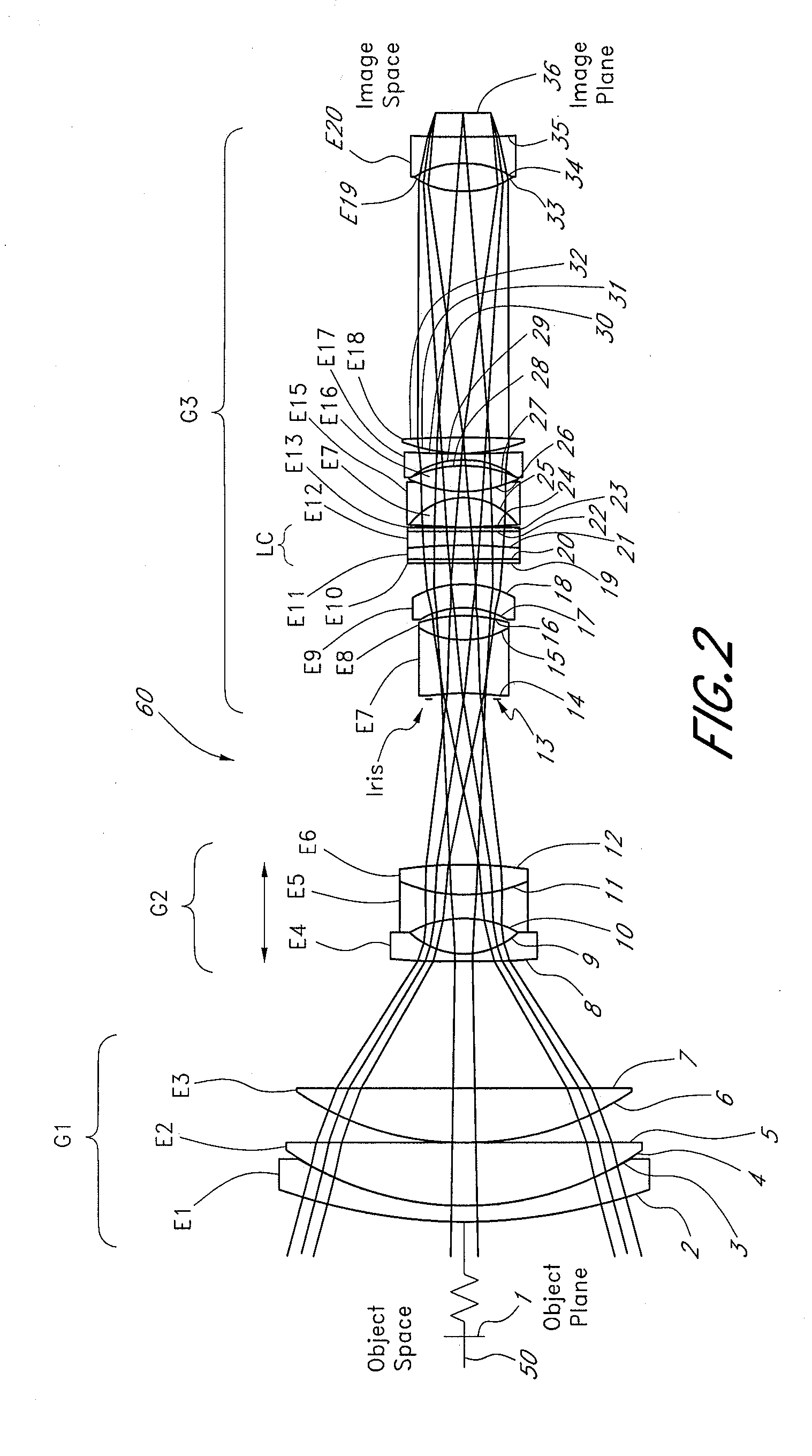
[0024]FIG. 1 illustrates a block diagram of a camera 100 with a zoom lens 102. A zoom lens is an assembly of lens elements with the ability to vary focal length. The individual lens elements may be fixed in place, or slide axially along the body of the lens. A lens group may consist of one or more lens elements. The individual lens elements may be constructed from solid-phase materials, such as glass, plastic, crystalline, or semiconductor materials, or they may be constructed using liquid or gaseous materials such as water or oil. At least one movable lens group provides variation of the magnification ...


PUM


Abstract

A high performance zoom lens system suitable for use with a camera is disclosed. The zoom lens systems employs liquid optics and a movable lens group to provide optical performance over the zoom focal length range at focus distances from close to infinity. The system also provides compensation for undesirable thermally induced effects by adjustments of the zoom group and the variably shaped optical surface in the liquid lens cell.

Description

RELATED APPLICATIONS[0001]This application is related to, and claims the benefit of U.S. Provisional 60 / 978,338 filed Oct. 8, 2007, the entirety of which is hereby incorporated by reference herein and made a part of the present specification.BACKGROUND OF THE INVENTION[0002]1. Field of the Invention[0003]This invention relates to an optical zoom lens system employing liquid optics.[0004]2. Description of the Related Art[0005]Imaging applications have historically used two or more movable zoom lens groups to provide zooming and different focal lengths. An additional lens group for focusing may also be needed.[0006]However, there are intrinsic disadvantages associated in using zoom and focus lens systems with moving lens groups. In particular, having moving zoom lens groups implies the need for complex mechanically moving parts. Each movable lens group requires support structures and drive mechanics such as cams and motors and in some cases control electronics to facilitate the moveme...

Claims


Application Information

Patent Timeline
Patent Type & Authority Applications(United States)
IPC IPC(8): G02B15/14
CPCG02B3/14G02B26/004G02B15/173G02B15/143105G02B13/009G02B15/1431G02B15/22
Inventor JANNARD, JAMES H.NEIL, IAIN
Owner MONUMENT PEAK VENTURES LLC
Why Eureka
Try Eureka