Lamp and method for supporting a light source

a technology of light source and light source, applied in the field of lamps, can solve the problems of large change in bulb-retaining force, inconvenient installation, swamping or overwhelming what,

Active Publication Date: 2009-04-09
SUNNE GUMMIFAB
View PDF1 Cites 68 Cited by
  • Summary
  • Abstract
  • Description
  • Claims
  • Application Information

AI Technical Summary

Benefits of technology

[0016]In an embodiment in which the concave side of the bridge region of the retainer contacts the convex rear surface of the bulb at the pivot end side of the bridge region but does not contact the convex rear surface of the bulb at the latch end side of the bridge region when the retainer is in its closed configuration, clearance between the retainer and the bulb rear surface at the latch end side of the bridge region when the retainer is in its closed configuration may be sufficient to prevent the latch end side of the bridge region from hitting the bulb rear surface during disengagement of the latch end of the retainer from the latch holder of the housing when the retainer is being moved from its closed to its open configuration.

Problems solved by technology

Moreover, a typical user, especially when in a hurry or frustrated by the challenge of simultaneously manipulating the free ends of the V-springs 990 to achieve proper installation without injury to fingers or lamp, may settle for incomplete or improper installation, as there is no positive or definitive mechanism to prevent the user from judging that the lamp is ready for use despite lost, unused, or improperly positioned V-springs 990.
Moreover, what little spring loading may exist with V-springs 990 will typically provide inadequate mechanical compliance, meaning that a small change in displacement, due for example to variation in part dimensions or installation technique or due to temperature change or impact, can result in a large change in bulb-retaining force, and may even swamp or overwhelm what compliance may exist, easily resulting in backlash or slop between parts.
In this way, any number of unsatisfactory conditions resulting from use of V-springs 990 may result in poor lamp performance or even light source failure due to loose or improper support of the bulb 905.
Thus, a heretofore unaddressed need exists in the industry to address the aforementioned deficiencies and inadequacies.

Method used


Image

  • Lamp and method for supporting a light source
  • Lamp and method for supporting a light source
  • Lamp and method for supporting a light source

Examples


Embodiment Construction

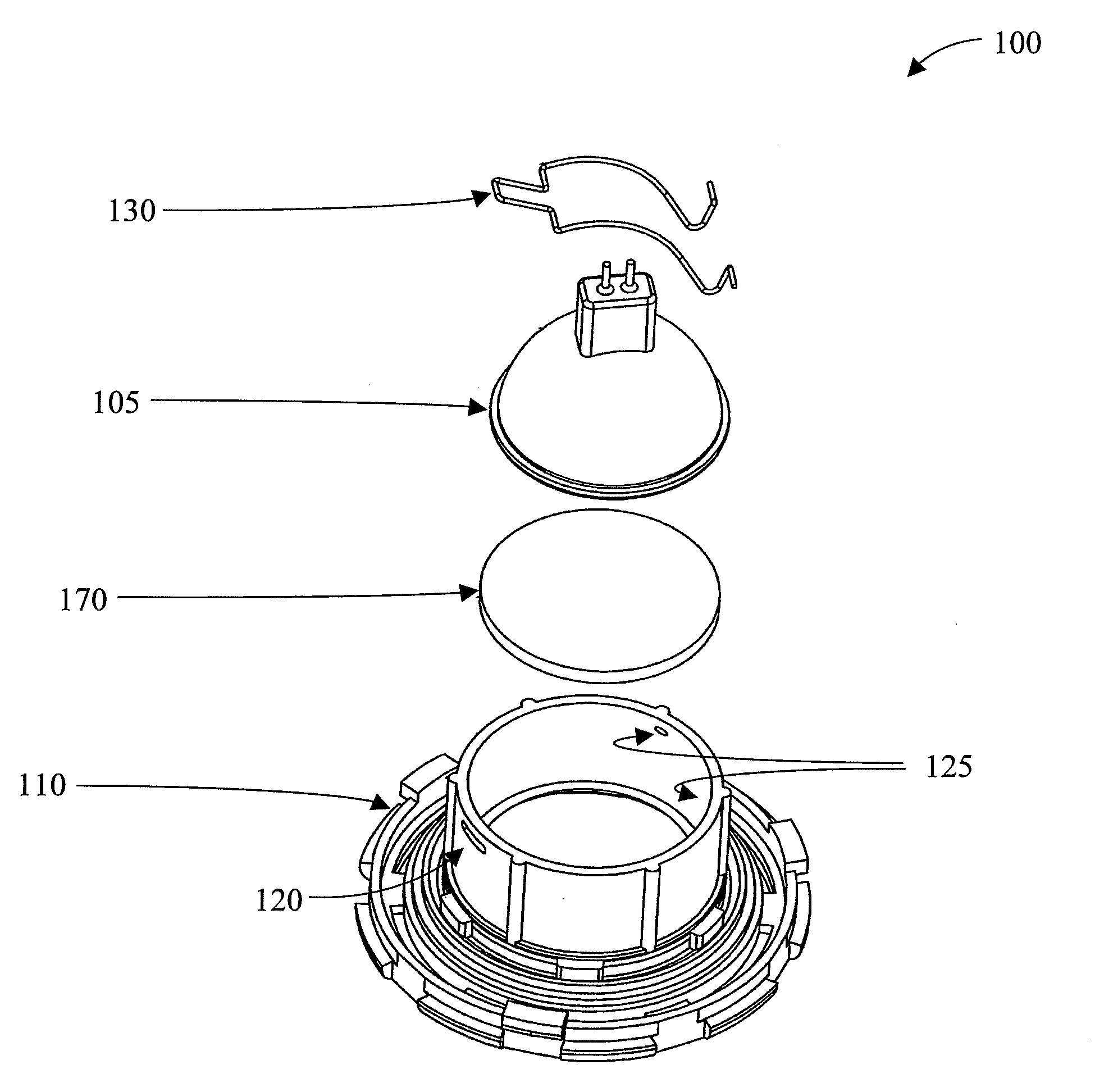
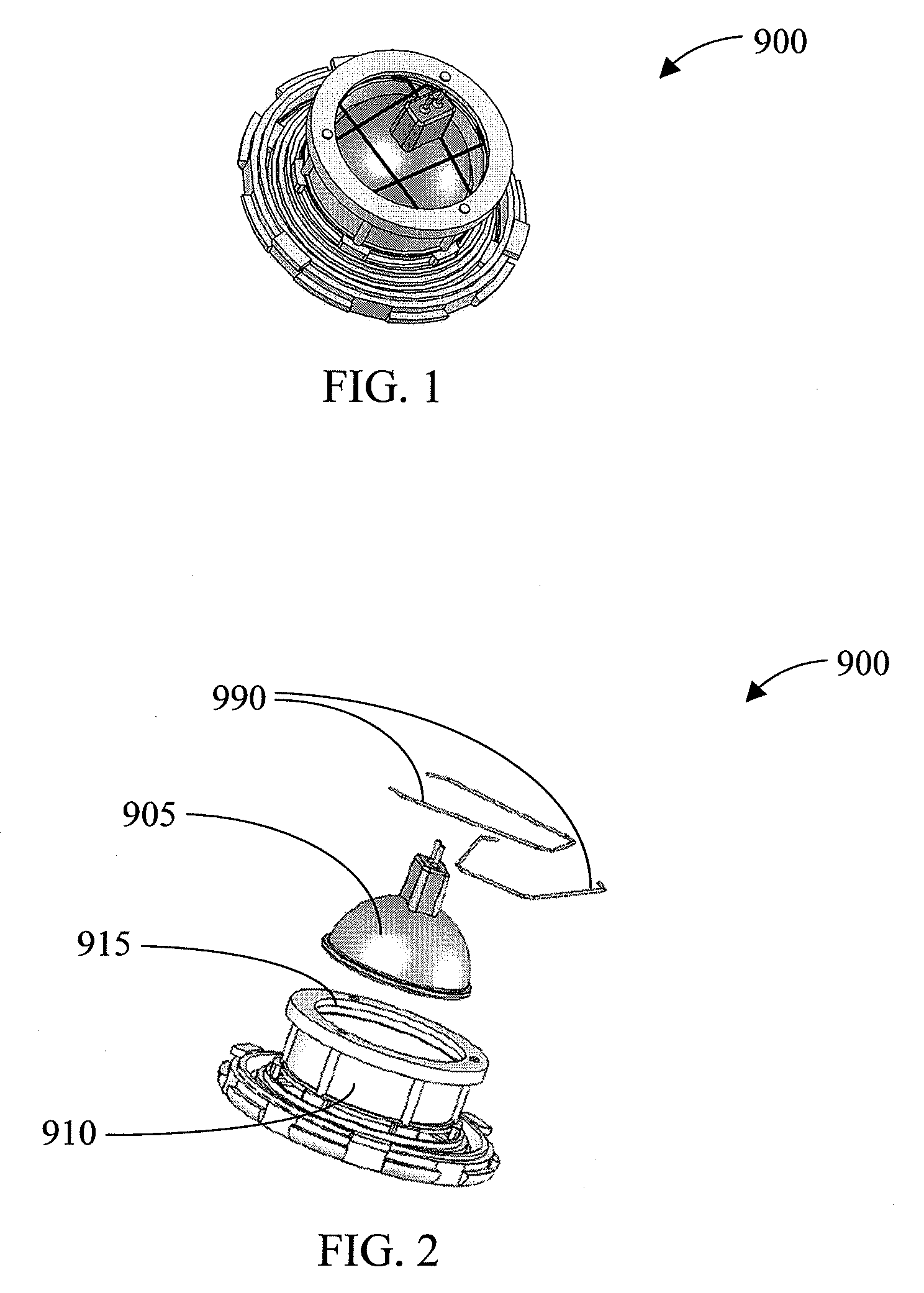
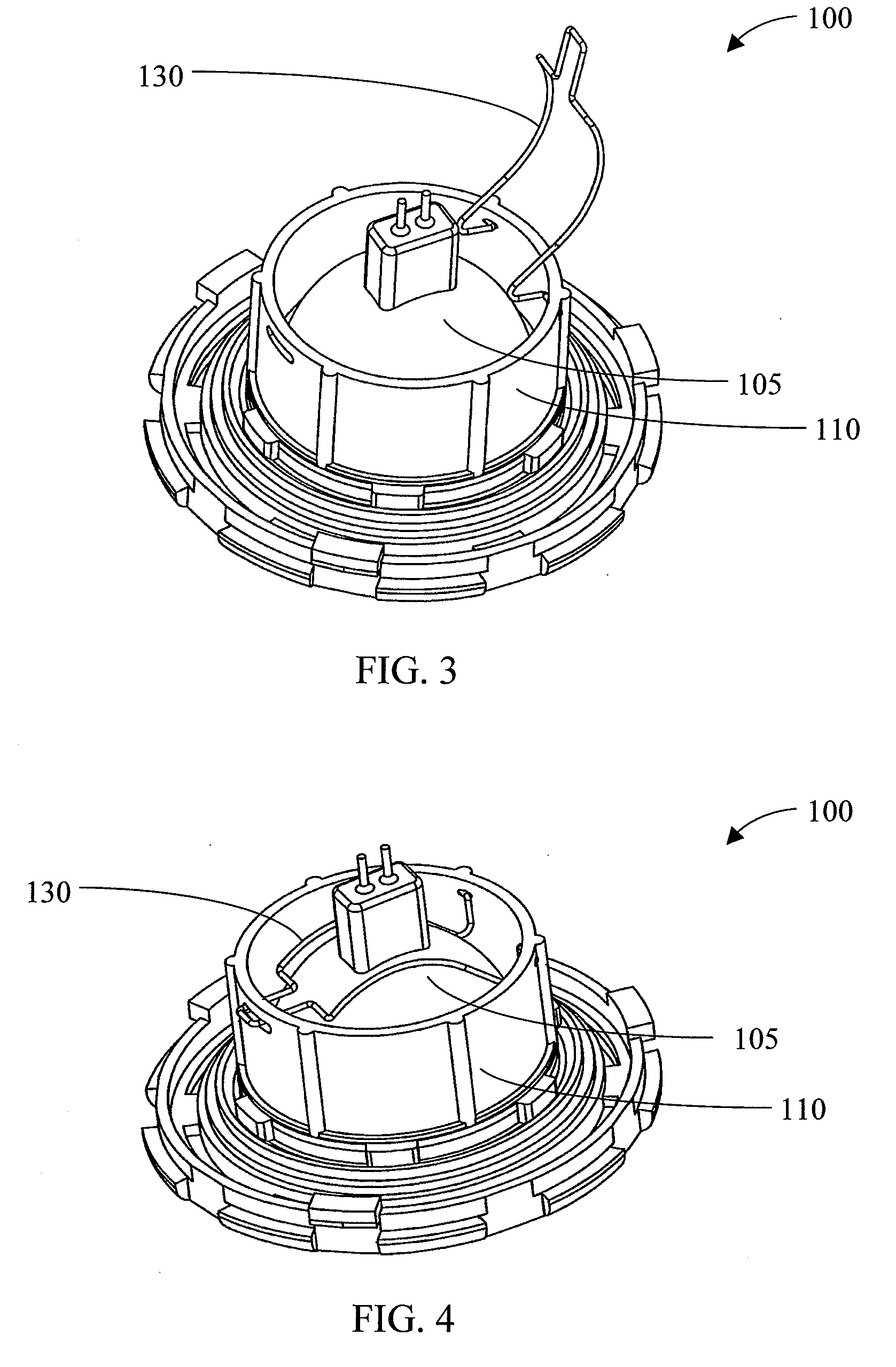
[0031]As used herein, the term “light bulb” (also referred to simply as “bulb”) refers to any light source capable of being installed in a lamp housing, without limitation with regard to shape except as otherwise specified herein. As used herein, except where otherwise clear from context, the term “lamp” refers to the combination of a housing, a retainer, and a bulb. As used herein, except where otherwise clear from context, the term “lamp assembly” refers to the combination of a housing and a retainer, regardless of whether a bulb is additionally present. As used herein, except where otherwise clear from context, the term “housing assembly” refers to the combination of a housing and a retainer.

[0032]The present invention provides a lamp or lamp assembly as well as a method for supporting a light source. For example, one embodiment of the present invention is a lamp such as might be used in dentistry or in a hospital emergency room for lighting when applying stitches or during a med...


PUM


Abstract

A lamp is provided. Generally, the lamp comprises light source means for providing illumination in a frontward direction, retainer means for applying a frontward-directed load to the light source, and housing means for mechanically supporting the light source means and the retainer means.

Description

CROSS-REFERENCE TO RELATED APPLICATION[0001]This application claims priority to copending U.S. Provisional Patent Application entitled “System and Method for Supporting a Light Source,” having Ser. No. 60 / 977,182, filed Oct. 3, 2007, which is hereby incorporated herein in its entirety by reference.FIELD OF THE INVENTION[0002]The present invention is generally related to a lamp, and more particularly is related to a lamp having a housing assembly employing a spring-loaded retainer to support and direct a light source.BACKGROUND OF THE INVENTION[0003]Lamps are often assembled by installing a light source in a housing. Examples of such lamps include examination lamps such as those used in dentistry or in hospital emergency rooms for lighting when applying stitches, for example, as well as lamps used in residential applications for spot lighting or lamps used in industrial applications for task lighting. Light sources used in such lamps may include halogen bulbs, light-emitting diode (h...

Claims


Application Information

Patent Timeline
Patent Type & Authority Applications(United States)
IPC IPC(8): F21V19/00
CPCF21V17/164F21Y2101/02F21V19/0005F21Y2115/10
Inventor JACOBSON, A. BRIANPANGREKAR, B. MAYUR
Owner SUNNE GUMMIFAB
Why Eureka
Try Eureka