Image forming apparatus

a technology of image forming apparatus and pressure member, which is applied in the direction of electrographic process apparatus, instruments, optics, etc., can solve the problems of image failure, and easy rise of pressure member temperature, so as to suppress the deterioration of image forming operation throughput and prevent excessive temperature rise of pressure member

Active Publication Date: 2009-04-09
CANON KK
View PDF12 Cites 15 Cited by
  • Summary
  • Abstract
  • Description
  • Claims
  • Application Information

AI Technical Summary

Benefits of technology

[0013]The present invention provides an image forming apparatus capable of preventing excessive temperature rise of a pressure member while suppressing deterioration of throughput of the image forming operation.

Problems solved by technology

However, if the fixing nip is made long, since an amount of heat that a pressure member receives from a fixing member is high, the temperature of the pressure member is prone to rise, and the temperature of the pressure member excessively rises and image failure is generated in some cases.
If the coated paper sheet is excessively heated, moisture in a base layer in the coated paper sheet is evaporated, and this water vapor bursts through a weak portion of the coat layer and is exposed.
As a result, the temperature of the pressure member rises excessively.
According to the apparatus disclosed in Japanese Patent Application Laid-open No. 2005-316397, however, since the problem is solved by the temporary separation of pressurizing operation, relatively long time is required for separating the pressure member and subsequent re-abutting operation against the fixing member.
That is, in order to suppress the temperature rise of the pressure member when time corresponding to a distance between sheets during the continuous printing operation is relatively short, the problem can not be solved by the temporary separation motion of the pressure member.
This is because that if the problem is to be solved by the temporary separation of the pressure member, time required for separating the pressure member and subsequent re-abutting operation against the fixing member becomes longer than time corresponding to a distance between sheets, and this deteriorates throughput of the image forming operation.

Method used


Image

  • Image forming apparatus
  • Image forming apparatus
  • Image forming apparatus

Examples


first embodiment

[Image Forming Apparatus]

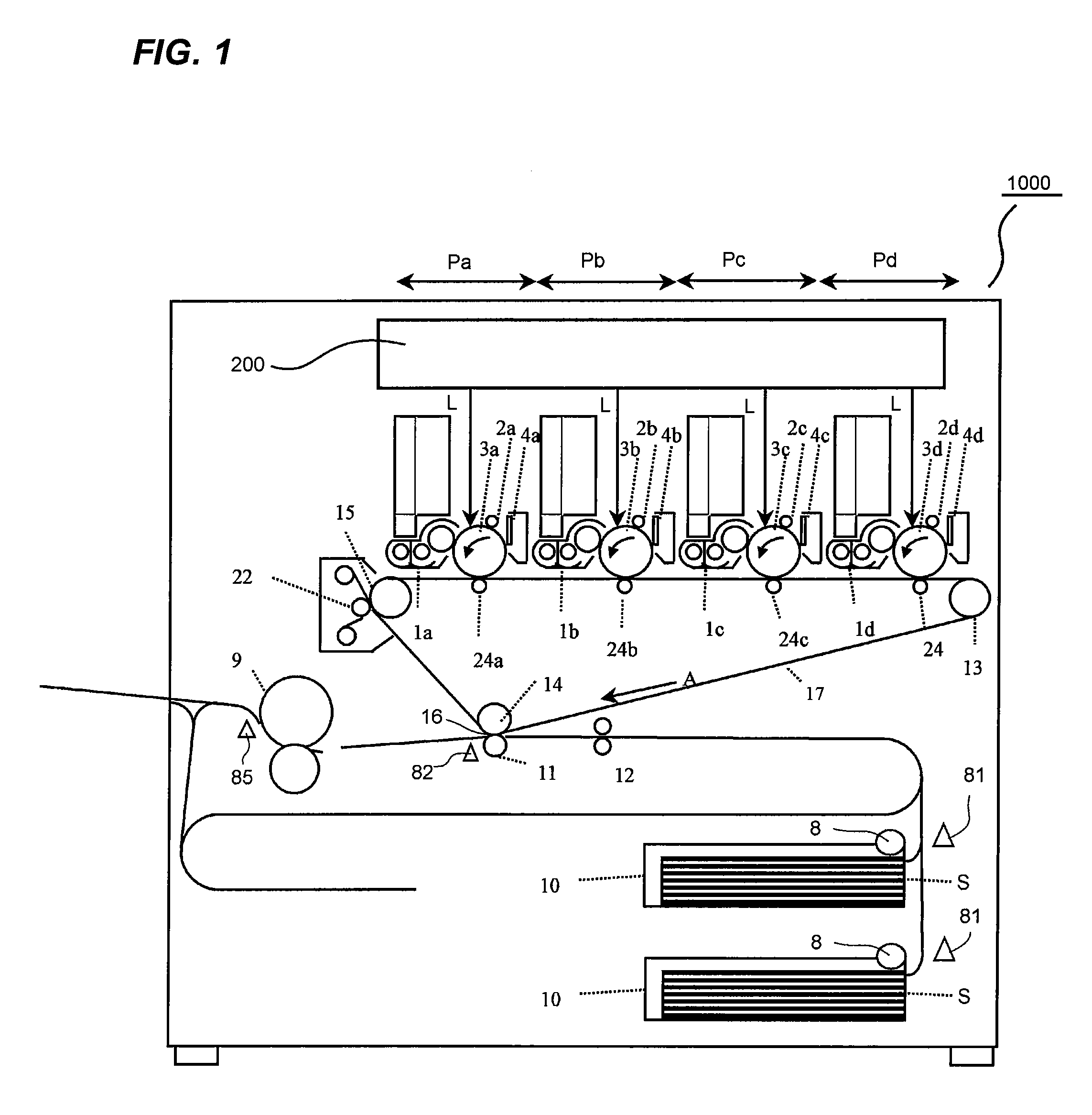
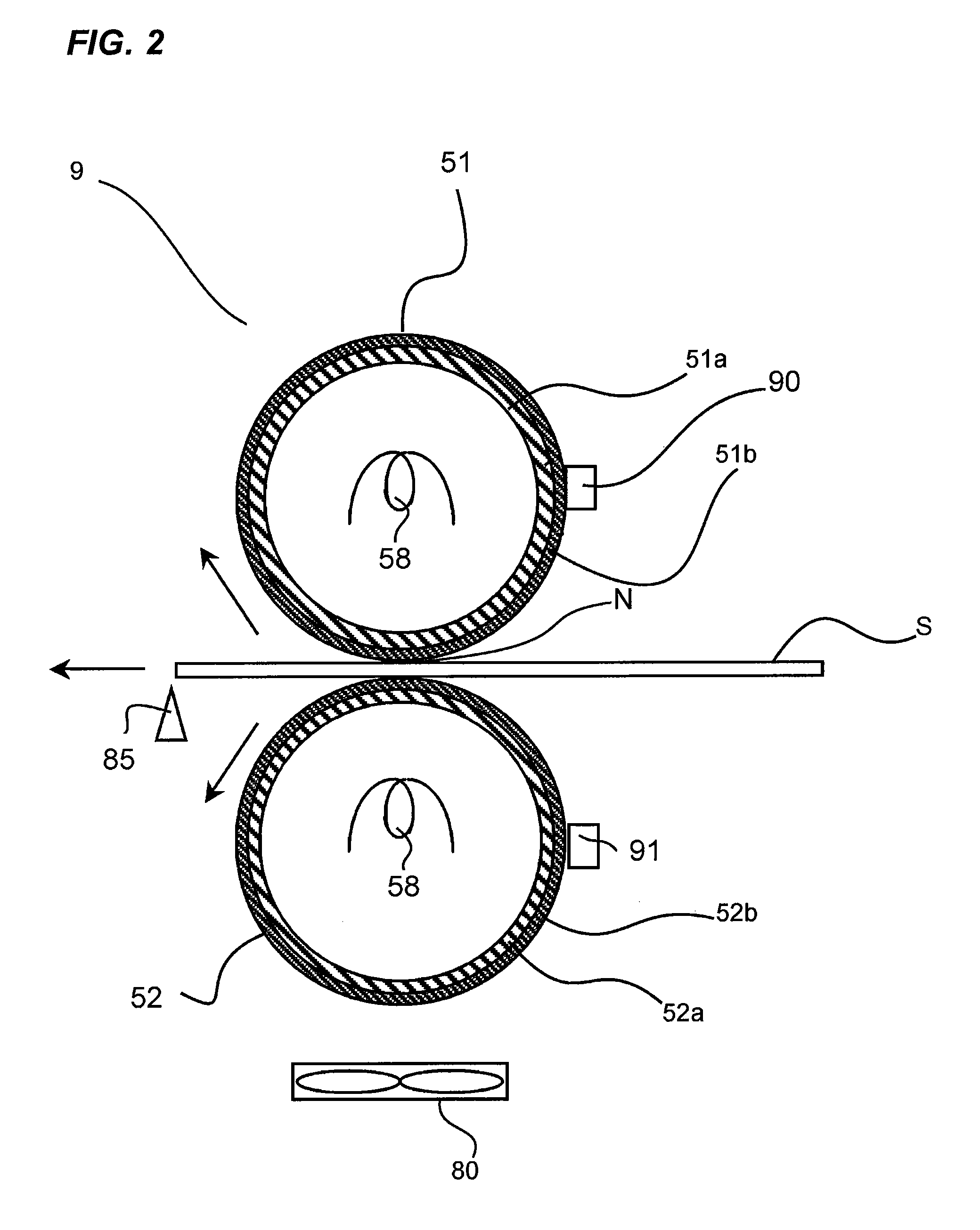
[0037]First, the entire structure of the image forming apparatus of the embodiment will be described together with the image forming operation with reference to FIG. 1.

[0038]In a main body of the image forming apparatus of the embodiment, first, second, third and fourth image forming portions Pa, Pb, Pc and Pd are provided, and a toner image having different colors is formed through processes such as electrostatic image, developing and transfer. The image forming portions Pa, Pb, Pc and Pd are the same except that the colors of toner are different. Hence, when it is not especially necessary to distinguish, subscripts a, b, c d which are added to the drawings for showing elements provided for colors will be omitted, and they will be described collectively.

[0039]The image forming portion P includes electrophotographic photosensitive drums 3 which are special image bearing members in this embodiment, photosensitive members. By developing an electrostatic image ...

second embodiment

[0105]Next, an apparatus according to a second embodiment will be described. Since the basic structure of the apparatus in the embodiment is the same as that of the previous embodiment, explanation thereof will be omitted, and a structure of a feature of the embodiment will be described. Members having the same functions as those of the previous embodiment are designated with the same symbols.

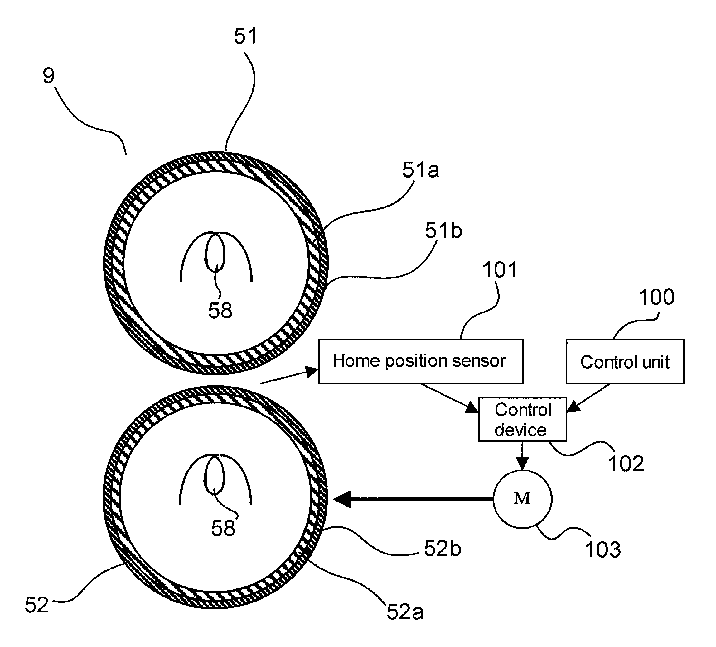
[0106]In the first embodiment, the plurality of sheet sensors 81, 82 and 85 are provided in the sheet conveying passage, and crimp, separating timing of the pressure roller 52 and acceleration / deceleration timing of the fixing roller 51 were determined.

[0107]In the embodiment, an image formation starting signal is sent from the image forming processing portion (controller) 300 to the image exposure apparatus 200, and time at which a recording sheet S reaches the secondary transfer portion 16 is obtained from the image writing timing at which the image exposure apparatus 200 starts the forming o...

third embodiment

[0138]Next, an apparatus according to a third embodiment will be described. Since the basic structure of the apparatus in the embodiment is the same as that of the previous embodiment, explanation thereof will be omitted, and a structure of a feature of the embodiment will be described. Members having the same functions as those of the previous embodiment are designated with the same symbols.

[0139]In this embodiment, the shortest time during which a recording sheet S reaches the fixing roller 51 is calculated from pickup timing of the recording sheet S from a supply deck, thereby selecting and determining the operation of the separation mode, the deceleration mode and the constant mode. A plurality of sheet cassettes 10 are disposed in the supply deck of the embodiment.

[0140]The pickup timing intervals of the recording sheets S are not always equal. For example, paper sheets in the sheet cassette 10 run out and the sheet cassette 10 is automatically changed to another sheet cassette...


PUM


Abstract

An image forming apparatus capable of executing a mode for decelerating a rotation speed of a fixing member and a pressure member between sheets in a continuous print than that during a fixing operation.

Description

BACKGROUND OF THE INVENTION[0001]1. Field of the Invention[0002]The present invention relates to an image forming apparatus which forms an image on a recording material.[0003]Especially, the invention relates to an image forming apparatus having a fixing member which heat-fixes a toner image on a recording sheet to a recording sheet by a fixing nip, and a fixing apparatus using a pressure member which comes into contact with the fixing member and forms the fixing nip.[0004]2. Description of the Related Art[0005]In recent years, on-demand print market which prints necessary number of commercial printed materials such as catalogs, posters, brochures and the like, or continuous prints while changing a portion of contents of print such as various debit notes and direct mails is increasing. In the on-demand print market also, an electrophotographic system image forming apparatus is in the limelight in place of offset print which needs plate-making.[0006]Hence, in the electrophotographic ...

Claims


Application Information

Patent Timeline
Patent Type & Authority Applications(United States)
IPC IPC(8): G03G15/20
CPCG03G15/657G03G15/2039G03G15/2032
Inventor CHIYODA, YASUHARUITO, YOSHIKUNINAKAYAMA, TOSHINORI
Owner CANON KK
Why Eureka
Try Eureka