Disk rotor and method of manufacture

Inactive Publication Date: 2009-04-09
GENERAL ELECTRIC CO
View PDF17 Cites 15 Cited by
  • Summary
  • Abstract
  • Description
  • Claims
  • Application Information

AI Technical Summary

Benefits of technology

[0007]Disclosed herein are disk rotors and a method of manufacturing disk rotors capable of achieving higher AN2 values than current disk rotors. In one embodiment, a disk rotor comprises a hub having a bore, and a plurality of spoke segments radially extending from the hub, each spoke segment including a base portion being attached to the hub and a rim portion, wherein the rim portion includes one or more airfoils integrally formed t

Problems solved by technology

All the area at a radius outside the line 22 is incapable of supporting load stresses, and is therefore, considered dead load.
Moreove

Method used


Image

  • Disk rotor and method of manufacture
  • Disk rotor and method of manufacture
  • Disk rotor and method of manufacture

Examples


Embodiment Construction

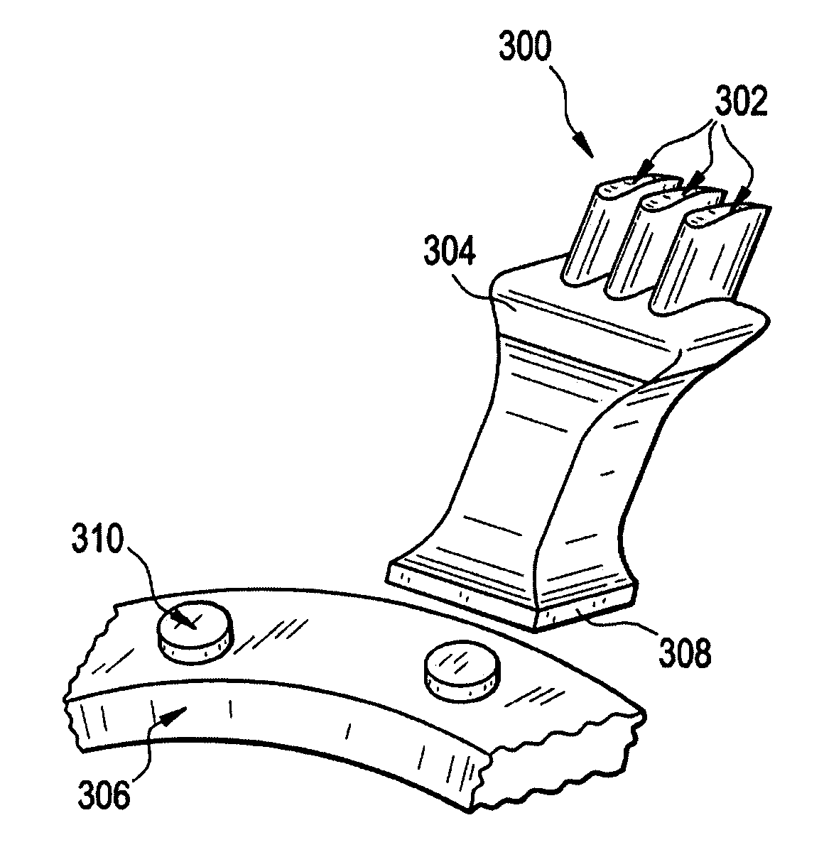
[0017]In one embodiment, a disk rotor having integral airfoils is disclosed. In another embodiment, a method of a manufacturing a disk rotor is disclosed, wherein the airfoils are integral and attached directly to the hub of the disk.

[0018]Referring now to FIG. 3, there is shown a rotor segment 100 of an exemplary embodiment of a disk rotor for use in a compressor or turbine application. The airfoils (i.e., blades) 102 are integral with the spokes 104. As shown in FIG. 3, the airfoil 102 and the spoke 104 form a single part, which can be welded to the hub 106. Each spoke is separated at the typical rim location to transmit airfoil load directly to the hub of the disk rotor.

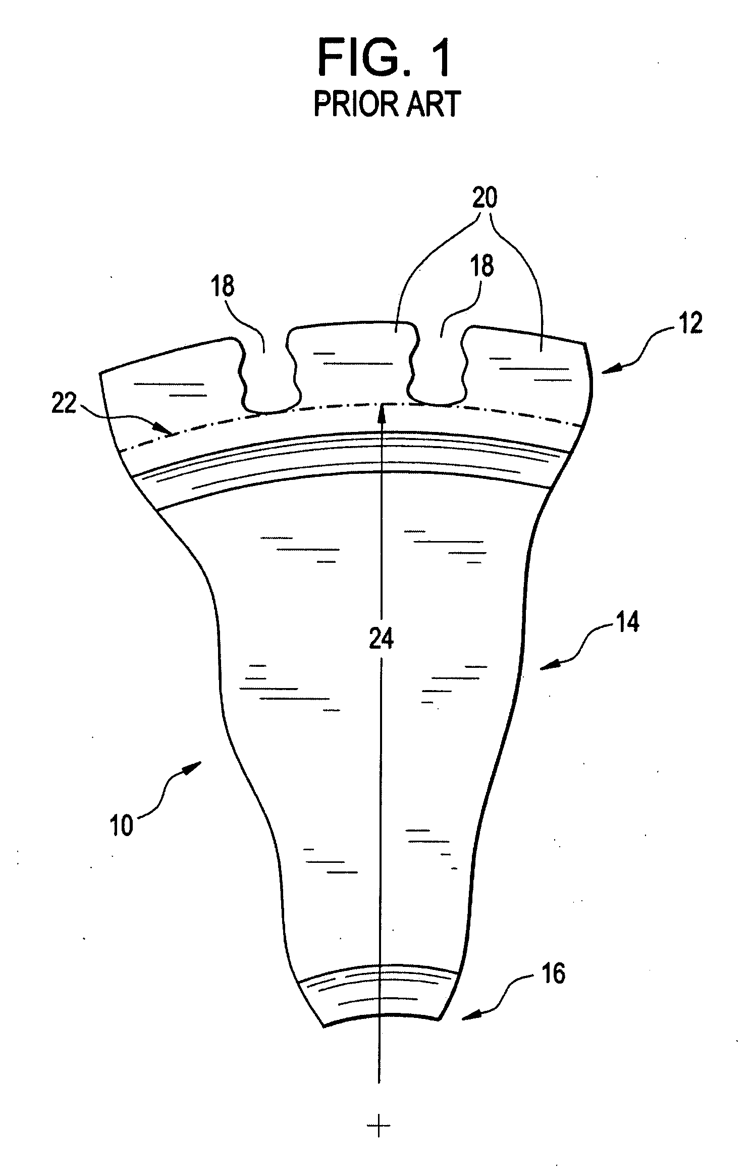
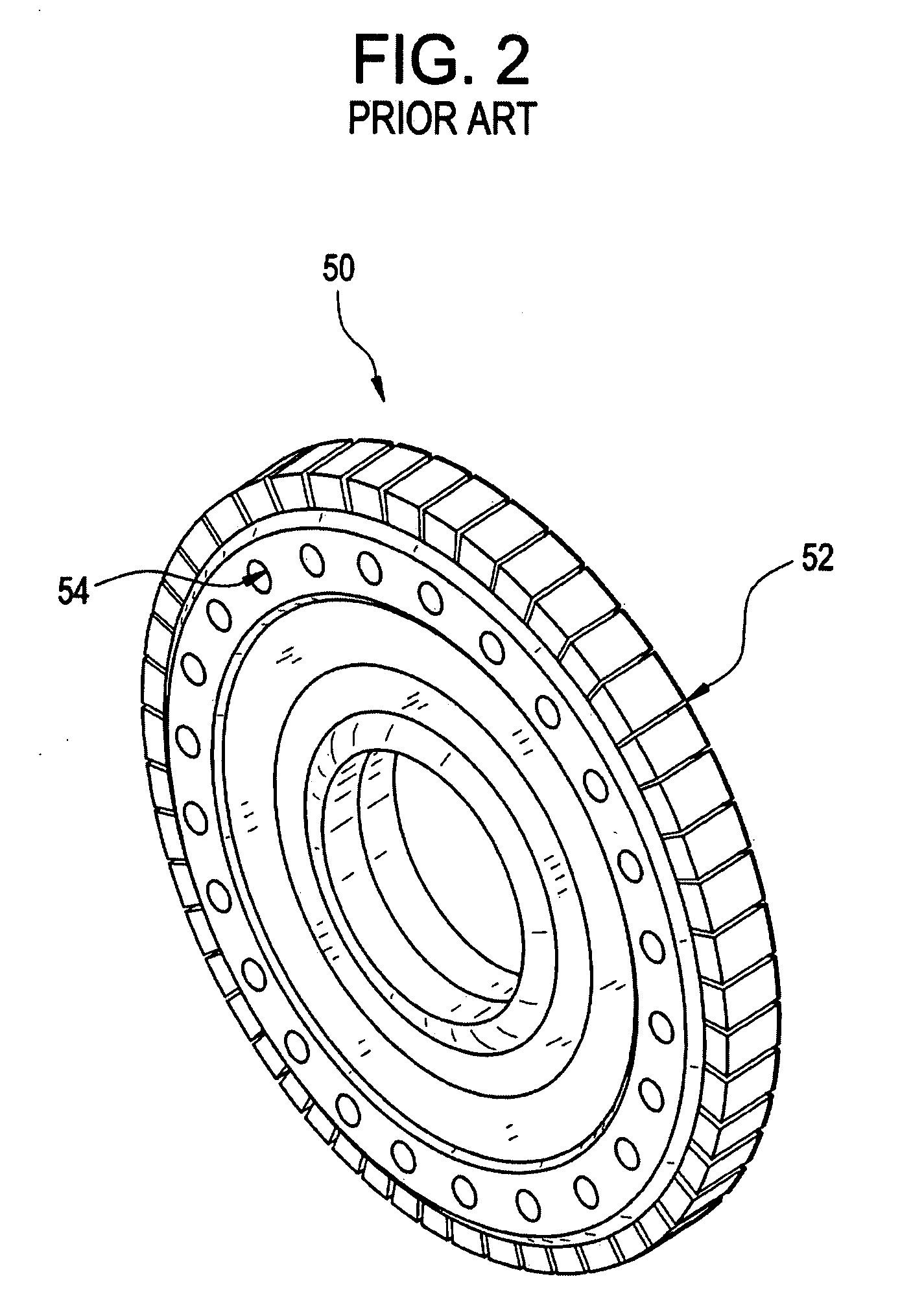
[0019]As described above, current disk rotors comprise a solid rim surrounding a web and a disk hub. The airfoils are then mechanically joined, e.g., by bolting, to attachment slots hollowed out within the rim. The disk rotor as disclosed herein comprises no mechanical attachments between the individual parts. Par...


PUM


Abstract

A disk rotor comprises a hub having a bore, and a plurality of spoke segments radially extending from the hub, each spoke segment including a base portion being attached to the hub and a rim portion, wherein the rim portion includes one or more airfoils integrally formed thereon, the plurality of spoke segments collectively forming a ring.

Description

BACKGROUND OF THE INVENTION[0001]The present disclosure relates to disk rotors, and, more particularly, to rotors having unique geometries for compressor or turbine applications.[0002]Typically in a compressor or turbine application, a rotor or a plurality of rotors are disposed in a shroud assembled circumferentially about an axial flow engine axis. The stationary shroud and rotor confines combustion gases to the gas flow path so that the combustion gas is utilized with maximum efficiency to turn the rotor. A typical rotor comprises a plurality of airfoils (i.e., rotor blades) attached to a disk hub.[0003]For some applications, such as in turbine engines, the turbine rotors require high AN2 values. AN2 values are a turbine rotor standard used to determine the capability of a particular rotor in a particular turbine engine application. “A” stands for the annulus area, i.e., the area swept out by the airfoil portion of the disk rotor. “N” represents the rotational speed of the airfoi...

Claims


Application Information

Patent Timeline
IPC IPC(8): F01D5/30
CPCF01D5/30F01D5/3061F05D2230/25Y02T50/671F05D2230/232F01D5/34Y02T50/60
Inventor CAIRO, RONALD RALPHDIMASCIO, PAUL STEPHEN
Owner GENERAL ELECTRIC CO
Why Eureka
Try Eureka